Chapter 3: Installation (Top-of-Floor)
Modes of Operation
(11/96)
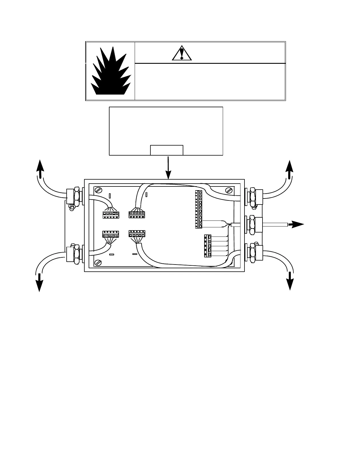
WARNING
DO NOT USE THE DigiTOL JUNCTION BOX
IN LOCATIONS CLASSIFIED HAZARDOUS
BY THE NATIONAL ELECTRICAL CODE
(NEC) ARTICLE 500.
* (Not compatible with Model 8510 Panel Mount DigiTOL Indicator or
Models 8572 and 8582 Counting Scales.)
** (Not compatible with Model 8530VS)
-EXC
-SIG
SHILD
+SIG
+EXC
-EXC
-SIG
SHILD
+SIG
+EXC
LC1
LC3
TO CELL 2
TO CELL 1
TO DigiTOL
INDICATOR
*8510
8520
8522
** 8530
JAGUAR
LYNX
-EXC
-SIG
SHILD
+SIG
+EXC
W 3
W 4
W 1
W 2
LC2
LC4
TB 1
TB 2
1
10
12
1
5
+20 VDC
GROUND
SHIELD
RXD A
RXD B
TXD B
TXD A
TO CELL 4
TO CELL 3
LC 2
LC 1
LC 4
LC 3
J-BOX
LOAD CELL ORIENTATION
(TOP VIEW OF PLATFORM)
TERMINAL NO POSITION FUNCTION WIRE COLOR
TB2 10 +20 VDC GREEN
TB2 12 GROUND BLUE
TB1 1 SHIELD ORANGE
TB1 2 RXD A RED
TB1 3 RXD B WHITE
TB1 4 TXD B YELLOW
TB1 5 TXD A BLACK
3-g
: Model 2160 DigiTOL Junction Box Wiring DLC Mode
Note: Jumpers W1, W2, W3 and
W4 must be “IN” shorting pins
(for 2 mV/V Load Cells).