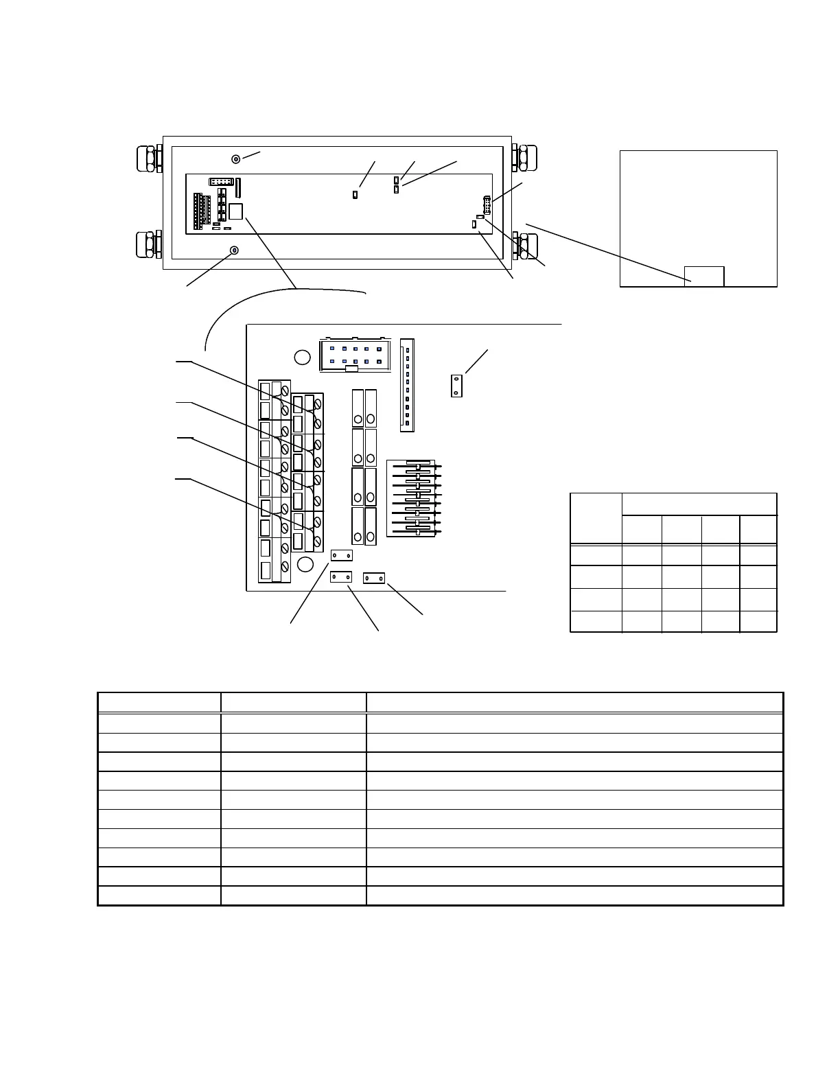
Chapter 3: Installation (Top-of-Floor)
Modes of Operation
(11/96)
Default Factory setting
Jumper Status Description
W1 Closed Matching the gain at 2 mV/V load cells
W2 Closed No external sensing (– SEN)
W3 Closed No external sensing (+ SEN)
W4 Closed Internal reference voltage = 3.5 V
W5 Open Excitation voltage for load cells = 4.0 Volts
W6 Closed Internal supply voltage = 7.1 Volts
W7 2-3 Protocol ID Net
W8 1-2 Interface 20 mA
W9 Open Supply voltage ID Net
SA1 Closed Trim Potentiometers Circuit Disabled
W 6
W 8 W 7
W4
W 3
W 2
W 5
P 7 P 8
P 1 P2
ST 2 ST 3
SA 1
P 3 P 5
-SIG + SIG
-EXC + EXC-SEN + SEN
8
7
6
5
4
3
2
1
LC 2
LC 4
LC 1
LC 3
Load Cell Orientation
( Top View of Platform)
LC 4
LC 3
LC 2
LC 1
W 1
W 9
Indicator Plug
LC 3 & 4
Ground Standoff
LC 1 & 2
Ground Standoff
1
2
3
4
5
6
7
8
9
TERMINAL
+Exc. -Exc. + Sig. -Sig.
Green Black White Red
CELL
#1
#2
#3
#4
4 4
9
9
3 3
8
7
2
2 7
8
1
1
6
6
Figure 3-i: Model 2162 ID Net Junction Box Wiring and Default Factory Setting