21
M7 – 11.607
User manual
www.vertidrive.nl
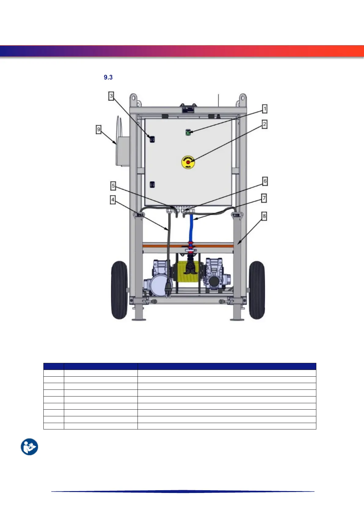
CONTROL BOX
Transport frame with control box
Green light turns on when the system is powered on.
Switch to shut down the system.
For opening and closing control box.
Main power supply of the system.
Power supply left drum winch (if applicable).
Power supply right drum winch (if applicable).
Cable power supply robot.
Power supply of the robot.
Supports frame and prevents transport frame from tipping over.
For manually winding up the cable
For detailed information about the transport frame and/or winch system please consult the User manual transport
frame / winch system