Liebert EXL S1 Installation
User Manual 10H52226UM60 - Rev. 1 - 01/2017
38
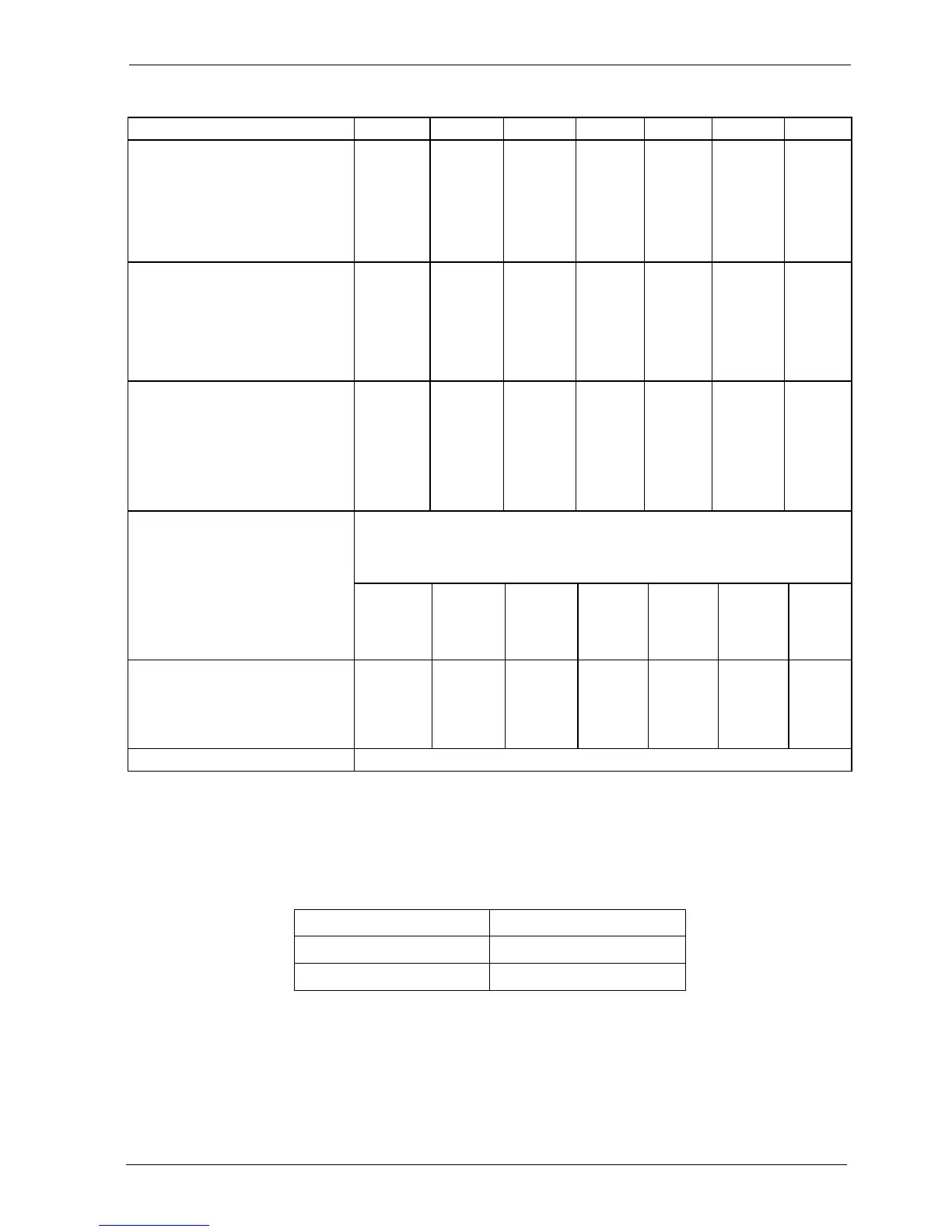
Table 1: Currents and maximum cable sizes
The following table lists the tightening torque for the hex-head terminal connection screws supplied
with the UPS.
Table 2: Tightening torque
UPS devices (kVA) 300 400 500 600 800 1000 1200
Primary Power line
Max. current (A)
1)
2)
Max. number of conductors
connectable to BUS-BAR & cross
section (mm
2
)
Screw size
1) For a nominal voltage of 380V, multiply the current value by 1.05; for 415V, multiply by 0.96
2)
Overload current specified in chap. 9
. on page 102 must be considered
473
2x240
M12
630
2x240
M12
788
2x300
M12
945
4x300
M12
1250
4x300
M12
1575
6x300
M12
1880
6x300
M12
Bypass Power line/Load
Nominal current (A)
2)
Max. number of conductors
connectable to BUS-BAR & cross
section (mm
2
)
Screw size
433
2x240
M12
577
2x240
M12
722
2x300
M12
866
4x300
M12
1155
4x300
M12
1443
6x300
M12
1732
6x300
M12
Battery, external +, -
Max. current (at 1.8V/cell - 240 cells)
(A)
3)
Max. number of conductors
connectable to BUS-BAR & cross
section (mm
2
)
Screw size
3) To select the cross section, see the actual installation data and national and local codes.
651
3x240
M12
868
3x240
M12
1085
4x300
M12
1302
6x300
M12
1736
6x300
M12
2170
8x300
M12
2604
8x300
M12
Neutral (N) from line power/ to load N
Coefficient for oversizing the neutral
line conductor when non-linear load is
supplied
1
Max. number of conductors
connectable to BUS-BAR & cross
section (mm
2
)
Screw size
4x240
M12
4x240
M12
4x300
M12
8x300
M12
8x300
M12
12x300
M12
12x300
M12
Ground
Max. number of conductors
connectable to PE BUS-BAR (mm
2
)
Screw size
1x240
M12
1x240
M12
1x300
M12
2x300
M12
2x300
M12
4x300
M12
4x300
M12
Type of connector BUS-BAR
Screw size Nm (+/-20)
M10 39
M12 68