Liebert EXL S1 CONNECTIVITY PANELS
User Manual 10H52226UM60 - Rev. 1 - 01/2017
70
appear on the display. To resume normal operation, the operator should turn EPO button to CLOSED
position, reset the fault on the display and turn on the UPS.
If this button is not installed, one jumper lead must be connected between pins 1 and 2.
For an indication of EPO status, connect pins 5, 6 and 7 to an external supervision system.
To ensure compliance of the wiring installation with European Harmonized Document HD384-4-46 S1,
an Emergency Switching Device (ESD) must be installed after the UPS.
1)
Contact Vertiv technical support for different configuration
The maximum cable diameter is 0.75 mm
2
.
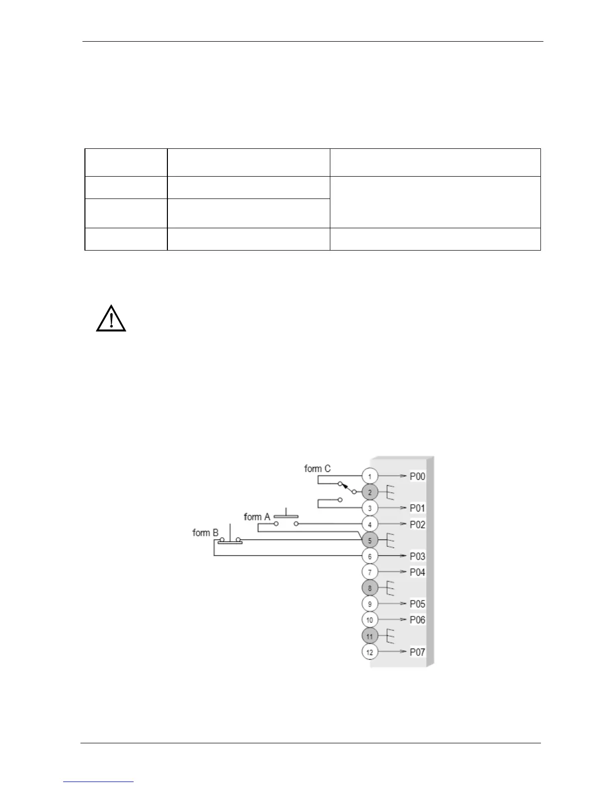
4.2.5. XP11 - Input Connector
Connection with customer plant:
12-wire connector used for dry contacts, only safe operating voltage should be connected here.
The current level for all inputs is less than 5mA at 12 or 24V.
Connection should be as follows:
PIN Signal Explanation
PIN 1-2 1° EPO INPUT EPO is ON when either input 1 or input 2 are
open; the inputs are independent and in OR
logic
1)
PIN 3-4 2° EPO INPUT
PIN 5-6-7 RPO Status CONTACT Form C dry contact. 1A @24 Vdc
Warning
The external Push-Button must be voltage free and isolated from all sources and GND.
The external EPO supervisor Input must not exceed 24V 1A.