PARALLEL CONFIGURATION Liebert EXL S1
87
User Manual 10H52226UM60 - Rev. 1 - 01/2017
7.3. Communication between UPS blocks
U
PS units exchange information through the connector cable (37 pin connector). Fig. 51 displays the
loop circuit, which is electronically monitored. The communication cables are shielded and must be
run separately and away from the power cables.
The CAN communication among the units will be possible only if two of the units making the parallel
are equipped with terminators over the CAN line.
The CAN bus termination can be set using jumper J2 over the Parallel Board; if the jumper is in
position 1-2 the terminator will be ON. When 3 or more units are connected in a parallel, remove the
exceeding terminators placing the jumper in position 2-3.
7.4. Parallel switching procedures
T
he following procedures refer to para 5.3. on page 75.
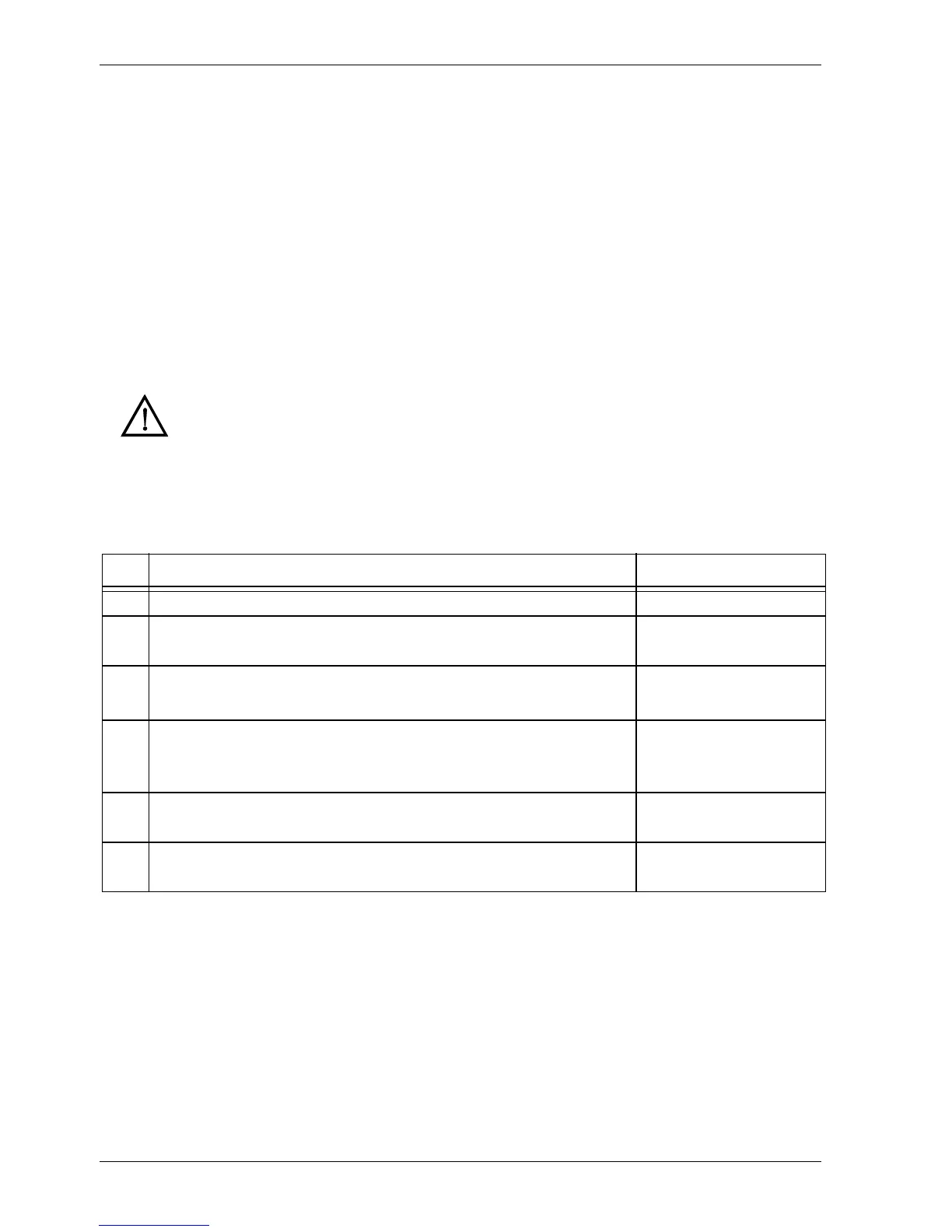
7.4.1. Procedure 1: UPS TURN-ON PROCEDURE
Starting with each UPS completely deenergized, this procedure explains how to switch on UPS units
and set them to Normal Operation Mode. On each UPS, perform the following procedure:
Warning
If static switch module and relative switches are not assembled, refer to MSS user
manual.
Step Action Status
1 Switch QS1 to the ON position Rectifier start up
2
Switch QS2 to the ON position (wait for Static Bypass Switch to
switch on)
Static Bypass Switch ON
and fans ON
3
Close external battery switches then set battery breaker
1)
to the
ON position
1) Not available for all ratings
4
Switch QS4 to the ON position
IMPORTANT: when switch QS4 is closed, the output of the UPS and
all the loads connected to it will be energized.
System in Bypass Mode -
Output voltage present
When the above steps have been completed for all the UPS units in
the parallel system:
5
Touch “Inverter On”.
At this point, the Inverters synchronize and take over the Load
Normal Mode (On Line)