............... 81
................. 81
5.7.2. Procedure 2: UPS TURN-OFF PROCEDURE ......................................................................... 80
........................ 80
5.7.1. Procedure 1: UPS TURN-ON PROCEDURE............................................................................. 80
............. 79
................... 79
....................... 79
5.6.1. Forming...................................................................................................................................................... 79
............................ 79
.................... 78
.......................... 78
.......................... 77
........................... 77
5.5. Operating modes.............................................................................................................................................. 77
....... 76
............................... 76
........................................ 75
...................... 75
....................... 75
................... 75
.......... 75
................ 75
....................................... 75
........................... 75
5.1.3. Bypass-line principal and overload management ............................................................. 74
.................... 74
.............................. 74
................................................ 74
SAFE OPERATION ...................................................................... 74
....... 72
4.2.9. XP4 - Battery Area Temperature sensor (input).............................................................. 72
4.2.8. X29 - Connector for Backfeed Status (Output) ................................................................ 72
4.2.7. XP31 - RJ-45 Ethernet interface for synchronization with external signal ....... 71
4.2.6. XP12 - Output Connector................................................................................................................ 71
....................70
.................. 69
............. 69
........ 69
.... 69
..................... 67
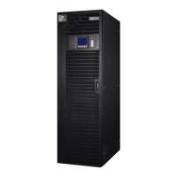
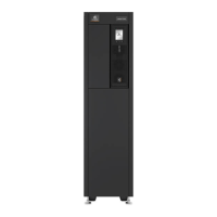
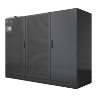
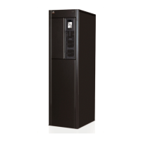
Liebert EXL S1
4 User Manual 10H52226UM60 - Rev. 1 - 01/2017
4.2. Customer connectivity panel...............................................................................................
4.2.1. XS3 - Slot for Connectivity Products....................................................................................
4.2.2. XS6 - Slot for LIFETM Products..........................................................................................
4.2.3. XP6 - Serial Interface for Connectivity Products (serial input/output).
4.2.4. XP10 - EPO connector ....................................................................................................
4.2.5. XP11 - Input Connector..................................................................................................
4.2.10. XP19A/B - SUB-D connector for parallel UPS connection.................................
5. NORMAL AND
5.1. Function..................................................................................................................
5.1.1. On-line Principle.......................................................................................................
5.1.2. Battery management ......................................................................................................
5.1.4. Communication...........................................................................................................
5.2. Special features..........................................................................................................
5.2.1. Safe and reliable operation .............................................................................................
5.2.2. Easy installation and operation .........................................................................................
5.2.3. Battery management ......................................................................................................
5.2.4. Environment, EMC........................................................................................................
5.2.5. Modern technology.......................................................................................................
5.3. Block diagram.............................................................................................................
5.3.1. Components..............................................................................................................
5.4. Maintenance Bypass Switch (not available for 600/800/1000/1200kVA)............
5.5.1. On-line operation .......................................................................................................
5.5.2. Battery operation .......................................................................................................
5.5.3. Bypass operation........................................................................................................
5.5.4. Maintenance Bypass......................................................................................................
5.6. Placement into service ....................................................................................................
5.6.2. Switch on the UPS.......................................................................................................
5.6.3. Connect the batteries ...................................................................................................
5.6.4. Switch to on-line operation .............................................................................................
5.7. UPS switching procedures ..................................................................................................
5.7.3. Procedure 3: TRANSFER FROM NORMAL MODE TO MAINTENANCE
BYPASS MODE ....................................................................................................................
5.7.4. Procedure 4: TRANSFER FROM MAINTENANCE BYPASS MODE TO
NORMAL MODE....................................................................................................................
 Loading...
