1Liebert PCW - UM - 273895 - 04.10.2018
1 - General Description
The Liebert
®
PCW is a full- featured precision air conditioner in-
tended for data centers, network closets, technological rooms (lab-
oratories, metrological rooms, museums), new and existing con-
structions, raised and non- raised oors, moderate to high density
heat loads, also in combination with cold aisle containments (up to
10 kW/Rack). It provides all the necessary functions of a standard
precision air conditioner, including cooling, heating, humidication,
dehumidication, air ltration, condensate management, tempera-
ture control, alarm functions and data communications. Liebert
®
PCW is designed on modular concept. Every Liebert
®
PCWunit is
composed (at least) of a coil section and a base or top fan section
with fan(s) installed on it.
The Liebert
®
PCW Standard Height Unit is supplied as a single unit
(height 1970mm), where coil and fan sections are connected.
The Liebert
®
PCW Extended Height is supplied in two modules,
the Coil Module (coil section)and the Fan Module (fan section). The
two modules should be connected on the eld (see chap. 3 Instal-
lation) (total height 2570 mm). The Fan Module is called Fan Base
Module when placed on the raised oor, Fan Base Frame when
installed in the raised oor, Fan Top Plenum when installed on the
top of the cooling unit.
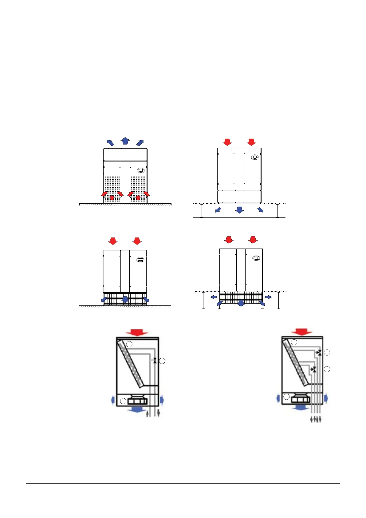
The units are available in the four congurations shown below.
Upow
Downow Up
Downow Down
Downow Frontal
1.1 - Single chilled water circuit - L- C versions
The unit is provided with a 2-way or 3-way modulating valve (1),
complete with incremental
motor for the control of water
ow to the coil (2); the open-
ing or closing signals, gener-
ated by the electronic control-
ler, manage the valve
actuator movement in order
to maintain the desired condi-
tions.
The room air is cooled pass-
ing through the coil (2) (air/
water heat exchanger),
moved by the motor fan (3).
The iCOM Control (or CDL
Graphic Display / opt.) con-
trols all parameters.
It is possible to adjust, for in-
stance: set points, proportional or proportional+integral tempera-
ture, integrating factor and valve characteristics.
It is also possible to manually adjust the valve with a suitable
wrench.
Chilled Water
(from Customer)
1
2
3
1.2 - Double chilled water circuit - X- R versions
The unit is equipped with two independent chilled water circuits in
cascade to one single coil, each cir-
cuit is equipped with 3-way/2-way
control valve (1), complete with incre-
mental motors for the water ow con-
trol of each circuit.
These units can be connected to
chilled water circuits coming from
two independent sources. In case
the rst circuit failure, the second one
can substitute the need for cooling
capacity and provide the necessary
back up.
The circuit 1 (valve located on the left
side, looking from the unit’s front) is
before the circuit 2 (valve located on
the right side, looking from the unit’s
front) on the air-stream.
1
1
Chilled Water
(from Customer)
1
1
2
3