13Liebert PCW - UM - 273895 - 04.10.2018
10)Continue xing the cable on the top front channel with the ap-
propriate cables ties.
If necessary use the inside part of the top front channel to keep the
loose cables in. Do not leave loose cables in the unit.
11) Close the electric panel. Make sure not to cut or damage the
electrical cable between the electrical panel and the unit. Use the
two hand wheels to close it.
12)Close the electrical panel with the electrical panel front cover
using the 4 screws.
6.4 - Power supply cable connection.
• Connect the cable to the Line inlet terminal board.
See Fig C power supply cable path.
For units with dual power supply option do not connect the
power cable supply as illustrated in g C; two supply cables
must be arranged and connected to the additional electrical
panel placed beside the main electrical panel.
• Use the cable size dened according to maximum current ab-
sorbed, the supply voltage, the installation type and the local
specication.
For unit with dual power supply both supply cables must be
dimensioned as described above.
• Protect the supply using a back- up fuse or circuit breakers.
• Do not t the supply cable in the raceways inside the machine
electric board.
• Use multi-polar cables with sheath(CEI20-22, IEC60332) only.
See electrical data in Enclosure B: Technical data tables.
For the units (in particular if the external display isn’t
installed)must be provided an external main switch,
easy to access, to facilitate, when necessary the unit
shutdown.
Fig. d - Power supply cable connection.
• Use the cable bushing on the back of the panel to get into the
electrical panel.
• Use cable tie to x the power supply cable to the electrical
panel back.
For cable entrance holes details see Enclosure E
Wiring connections (Fig. d):
• Connection for remote on- o must be done by the installer.
• The General Alarm terminals allow remote alarm signaling.
In case of short circuit, check the sticking of the involved switch
and replace it.
Cable ties
Cable bushing
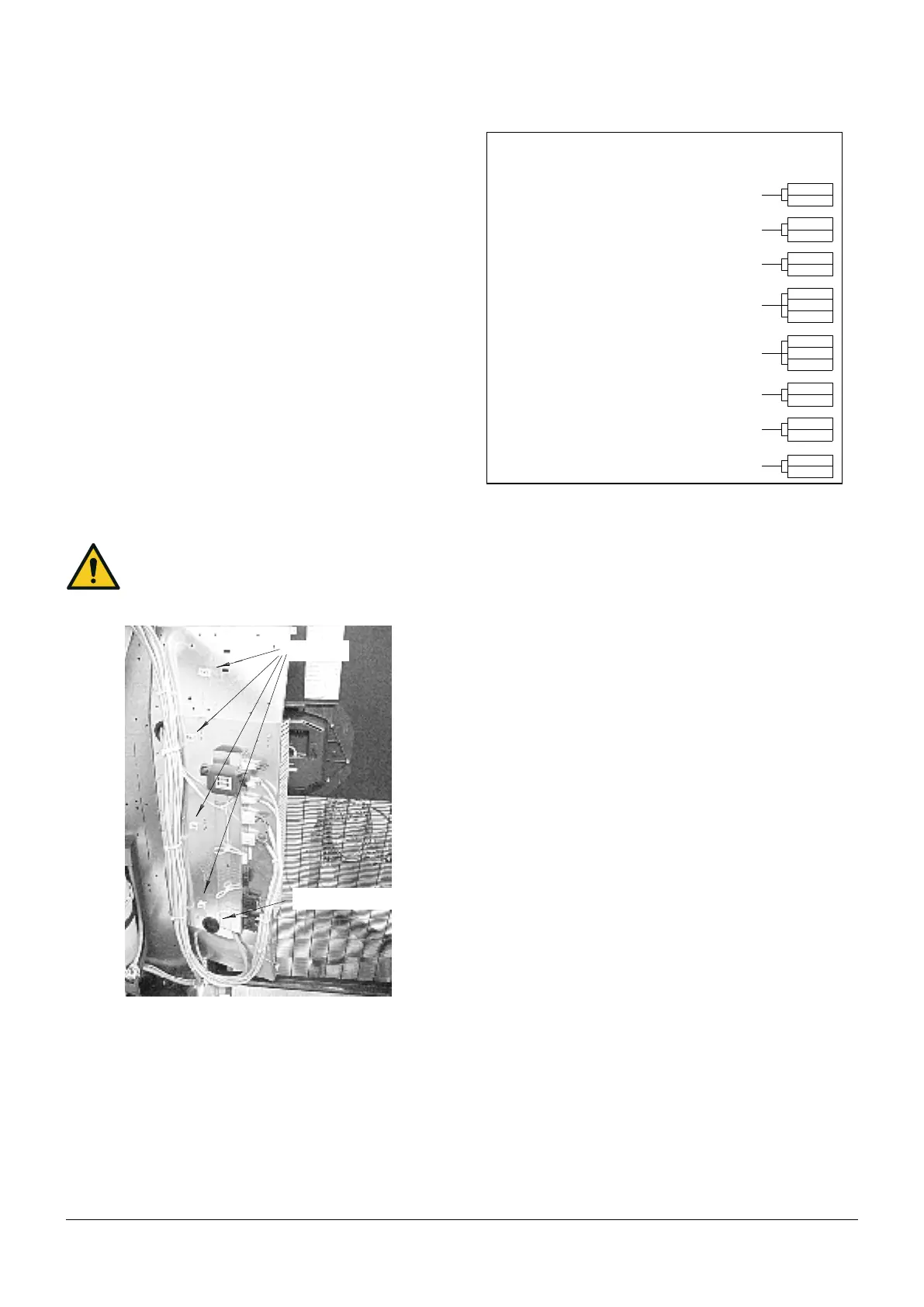
Fig. e - Available terminals
6.6 - Protective features of EC fan
The EC fan has been provided with the following protective fea-
tures:
• Over temperature of electronics
• Over temperature of motor
• Locked rotor protection
• Short circuit at the motor output
With any of these failures, the motor stops (electronically-no poten-
tial separation), the status relay is released.
NO automatic restart. To reset the alarm, power supply has to be
switched o for min. 20s once motor is at standstill.
• Mains under- voltage detection: if mains voltage falls below
3ph/290Vac (typical value) for 5 s minimum, motor will be
switched o (only by electronics, no potential separation), sta-
tus relay is released.
If mains voltage returns to correct values, the motor will
restart automatically.
• Phase failure recognition: if one phase fails for 5s minimum,
motor will be switched o (only by electronics, no potential
separation), status relay is released.
If all 3 phases return to correct values, the motor will re-
start automatically within 10- 40 s.
The power supply for an external speed setting potentiometer is
short-circuit protected.
Motor is overload- protected via motor current limitation.
Warning! Leakage current of the motor is approx 7 mA.
7 - Start- up
7.1 - First start - up
(or after long standstill)
Start the air conditioner as follows:
1) Open all valves in the water circuit according to the instruction
label attached to the valve.
2) Check that there are no water leakages.
53
52
61
63
105
106
51
53
400 (NC)
401 (C)
402 (NO)
70
71
61
62
UXILI
RY TERMIN
L BOX
300 (NC)
301 (C)
302 (NO)
WARNING
(300- 301 NC = warning or unit o)
clogged lter (CF)
(CLOSE = OK)
remote on- o
(CLOSE = ON)
water leakage (LWD)
GENERAL ALARM
(400.401 NC = alarm or unit o)
smokestat restat (AAP)
optional (CLOSE = ON)
operating fa n
(CLOSE = ON)
user alarm (or AAP)
(OPEN = ALARM)