15Liebert PCW - UM - 273895 - 04.10.2018
9 - Calibrations
The air conditioner has already been factory- tested and calibrated
as shown in Enclosers B.
9.1 - Chilled water valve
The 3 way or 2 way valves control the chilled water ow; they are
connected with dierent actuators according to the valve options:
standard pressure valve, High pressure valve and 0 - 10V valves.
The actuator controls the valve opening by a stem. When actuator
stem is completely down, the valve is open and chilled water coil
is supplied.
The valve running time is set to the value specied in the Control
Manual
PH025- PH046*:
• When the valve is fully open
(i.e. max. chilled water ow) the
actuator slot is set to ’1’.
• When the valve is closed (i.e.
no chilled water ow) the actua-
tor slot is set to ’0’.
In the unlikely event of control sys-
tem failure, the valve can be manu-
ally controlled by means of the rota-
ry knob. It can be used to drive the
actuator into any position between 0
and 1.
* PH035- 040- 046: in the options 2 way High Pressure Valve
and 3 way High Pressure Valve, consider the units as PH045-
PH201.
0
1
0
1
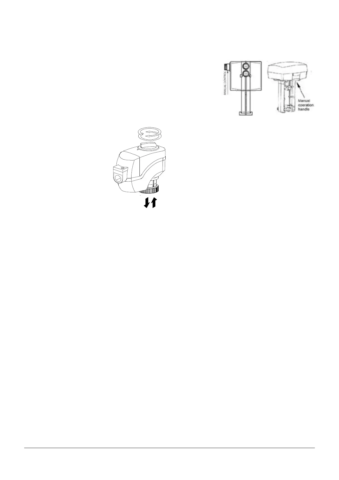
PH045- PH201:
Check the actuator stem to control the valve opening.
Actuator stem full up, valve is closed (i.e. no chilled water ow).
Actuator stem full
down, valve is fully
open (i.e. max.
chilled water ow).
In the unlikely event
of control system
failure, the valve
can be manually
controlled by means
of apposite manual
control on the valve.
For more details see also technical bulletin of chilled water valves
and related actuators. Technical bulletins are enclosed with docu-
mentation on board of the unit.
9.2 - Water leakage sensor (Liquistat)
Due to high ooding alarm device sensitivity, to the end to avoid un-
desirable alarm signal because of few sporadic water drops, place
the sensors at a minimum distance of 50 cm from the unit base
perimeter.
This solution assures alarm intervention for real ooding risk only.
9.3 - Environment protection
A misuse or an incorrect calibration of the unit leads to increased
energy consumption, resulting in an economic and environmental
damage.