4Liebert PCW - UM - 273895 - 04.10.2018
2.8 - Unit Weight
Tab. c - Unit Weight
(1) For Extended Height version the total unit weight must be calculated by adding
the Coil Module weight and Fan Section weight.
3 - Assembly
The PCW Standard Height Unit is supplied already assembled;
the PCW Extended Height is supplied in two modules, the Coil
Module and the Fan Module. The unit modules must be connect-
ed on the eld close to the nal working unit position.
Make sure you have the space available for mounting operations.
After the assembly the unit can be moved and positioned in the
working site. See point 4 Positioning.
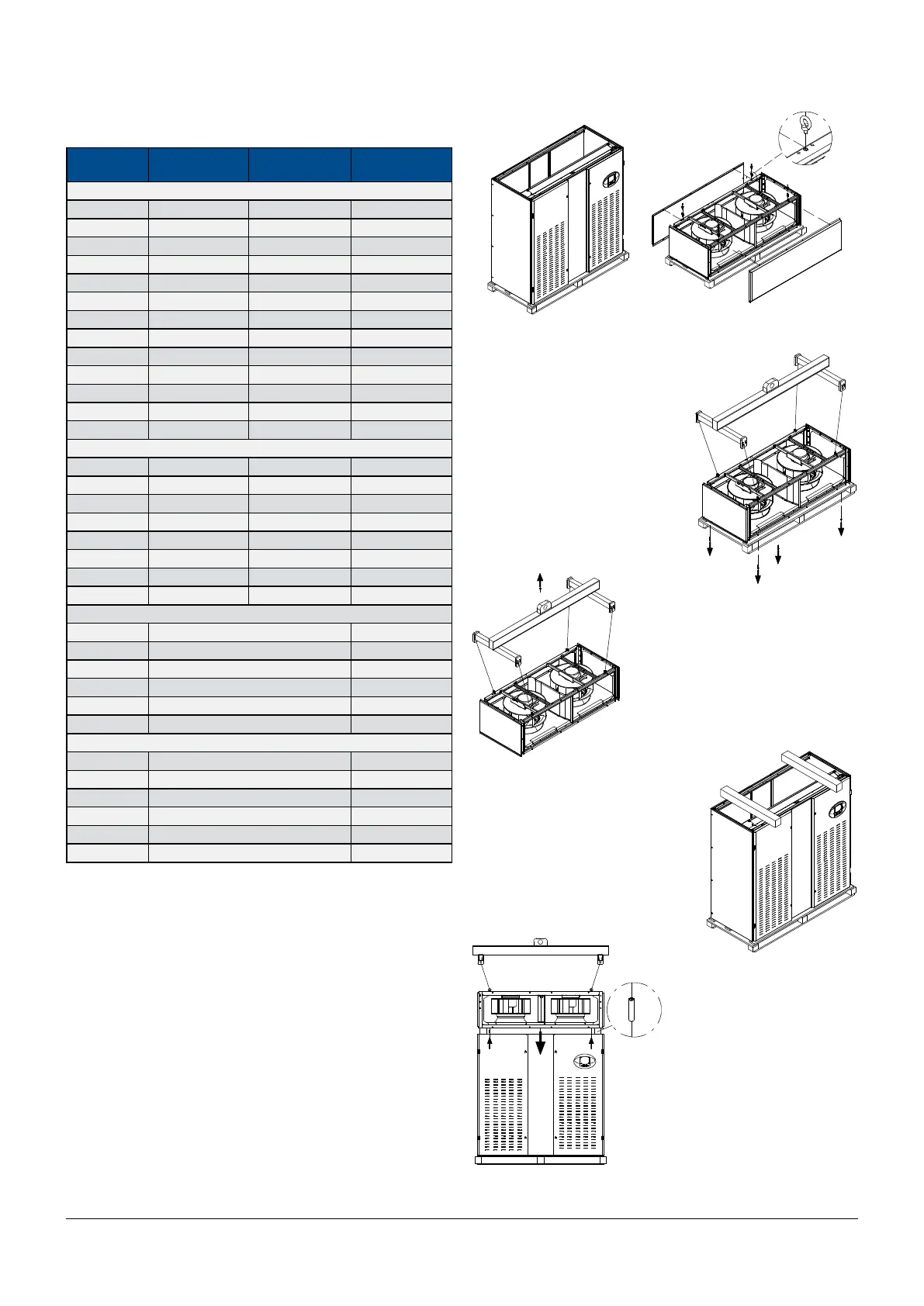
3.1 - Extended Height unit: Upow
1) Place the two modules (coil module and fan top plenum) close to
the nal position.
Models
Single circuit
unit [kg]
Double circuit
unit [kg]
Packaging
[kg]
Standard Height Unit
PH025 310 - 19
PH030 320 - 19
PH035 356 - 23
PH040 373 396 23
PH045 481 - 28
PH060 511 552 28
PH070 582 - 31
PH080 598 627 31
PH095 680 - 42
PH100 700 - 42
PH110 740 753 42
PH145 853 866 47
PH170 955 968 58
Extended Height unit [Coil Module]
(1)
PH046 276 326 23
PH066 410 483 28
PH081 420 - 31
PH091 462 500 31
PH111 515 - 42
PH136 575 618 42
PH161 660 673 47
PH201 720 733 58
Extended Height unit [Fan Base Frame]
(1)
BF120 91 26
BF175 150 35
BF205 170 41
BF255 218 54
BF295 245 61
BF335 325 78
Extended Height unit [Fan Base Module/Fan Top Plenum]
(1)
BM/ TP 120 132 26
BM/ TP 175 200 35
BM/ TP 205 230 41
BM/ TP 255 286 54
BM295 340 61
BM335 405 78
2) Remove the front and back panels from the fan top plenum.
Insert 4 shackles (M8, not supplied) in the upper frame.
3) Remove 4 bolts from the fan
top plenum pallet, two on each
side, if not already done (see
chapter 1.7).
4) Lift the fan top plenum using
slings and a 4 point lifting bar
(not supplied).
5) Put two timber pieces on the
coil module and place the fan
module on them.
6) Insert 4 dowels (M8) in the
lower frame of the fan top ple-
num.
7) Run the EC Fan power cable
positioned in the coil module
through the cable bushing to
the fan module. Then run the
EC Fan signal cable (and Elec-
trical Heater cable if installed)
positioned in the fan module
through the cable bushing into
the coil module. See chapter 6
for Electrical connection details.