2Liebert PCW - UM - 273895 - 04.10.2018
1.3 - Operating limits
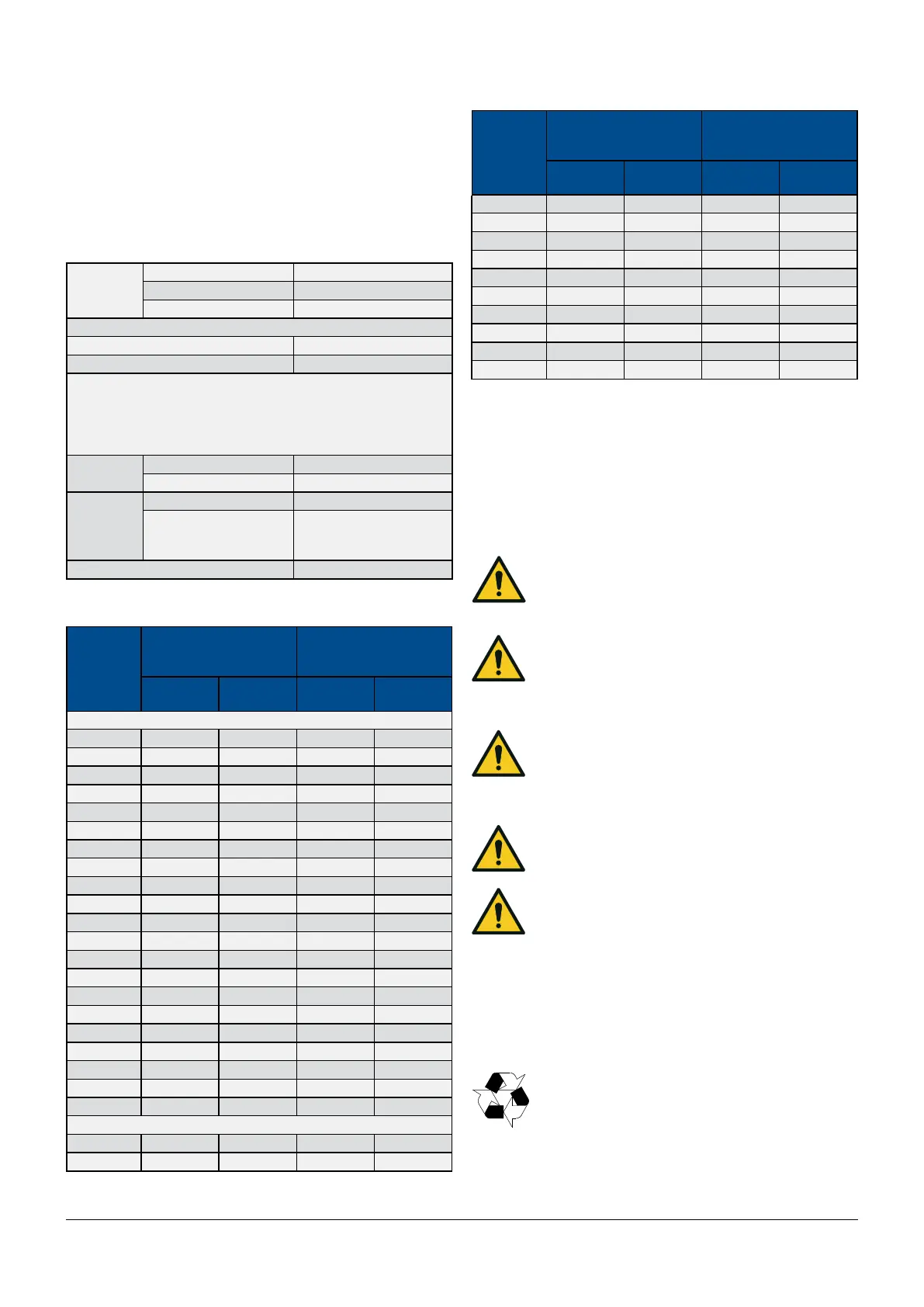
The units are designed to operate within working ranges (see Tab.
a).
These limits are referred to new machines or to those that have
been correctly installed and serviced.
The warranty clauses are no longer valid for any possible damage
or malfunction that may occur during or due to operation outside
the application values.
Tab. a - Operating limits
Tab. b - Max dierential pressure on the modulating valve.
Room air
conditions
Temperature: From 18°C to 40° C
Humidity ratio From 5.5 g/kg to 11 g/kg
Relative humidity From 20% to 60%
Chilled water circuit
inlet water temperature min. 5°C
water pressure max. 16 bar
Max. dierential pressures on the modulating valve (2 or 3
ways) (see Tab. b)
- Max. dierential pressure through the closed valve: Δpcv
- Max. dierential pressure across the valve for modulating
service: Δpms
Hot water
circuit
inlet water temperature max. 85°C
water pressure max. 8.5 bar
Storage
conditions
Temperature: From -20°C to 50° C
Relative humidity
Max. 90% RH, prevent-
ing surface condensa-
tion.
Power supply tolerances V ± 10% Hz ± 2
1.3.1 - Noise level limits
The sound pressure level in free eld at 1.5mheight and 2m in front
of the air conditioner, with fan in operations, is less than 70 dBA for
all models.
2 - Preliminary operations
2.1 - Safety Information
WARNING!
Risk of top- heavy unit falling over! Improper handling
can cause equipment damage, injury, or death! Read
all of the following instructions before attempting to
move, lift, remove packaging from, or preparing unit for installation.
CAUTION!
Risk of sharp edges, splinters and exposed fasteners!
Can cause personal injury! Only properly trained per-
sonnel wearing appropriate safety headgear, gloves,
shoes and glasses should attempt to move, lift, remove packaging
from the unit or prepare the unit for installation.
CAUTION!
Risk of overhead interference! Can cause unit and/or
structure damage! The unit may be too tall to t through
a doorway while on the skid.
Measure the unit and doorway heights and refer to the installation
plans prior to moving the unit to verify clearances.
CAUTION!
Risk of unit damage if improperly stored! Keep the unit
vertically upright, indoors, and protected from damp-
ness, freezing temperatures, and contact damage.
ATTENTION!
The conditioner must never be installed out of doors.
See drawings in Enclosures C.
2.2 - Equipment Inspection
Upon arrival of the unit, and before unpacking, verify that the la-
beled equipment matches the Bill of Lading. Carefully inspect all
items for either visible or concealed damage. Damage should be
immediately reported to the carrier and a damage claim lled in
with a copy sent Vertiv or to your sales representative.
2.3 - Packing material
All material used to package this unit is recyclable.
Please save for future use, or dispose of the material
appropriately.
Models
Standard Pressure
Valve
0- 10V valve
High pressure valve
Dpcv
(kPa)
Dpms
(kPa)
Dpcv
(kPa)
Dpms
(kPa)
Single chilled water circuit
PH025 - - 300 300
PH030 - - 300 300
PH035 175 175 940 200
PH040 175 175 940 200
PH045 300 200 650 200
PH060 300 200 650 200
PH070 210 200 490 200
PH080 210 200 490 200
PH095 210 200 490 200
PH100 210 200 490 200
PH110 210 200 490 200
PH145 210 200 490 200
PH170 210 200 490 200
PH046 175 175 940 200
PH066 300 200 650 200
PH081 210 200 490 200
PH091 210 200 490 200
PH111 210 200 490 200
PH136 210 200 490 200
PH161 210 200 490 200
PH201 210 200 490 200
Double chilled water circuit
PH040 175 175 - -
PH060 300 200 650 200
Models
Standard Pressure
Valve
0- 10V valve
High pressure valve
Dpcv
(kPa)
Dpms
(kPa)
Dpcv
(kPa)
Dpms
(kPa)
PH080 300 200 650 200
PH110 210 200 490 200
PH145 210 200 490 200
PH170 210 200 490 200
PH046 175 175 - -
PH066 300 200 650 200
PH091 300 200 650 200
PH136 210 200 490 200
PH161 210 200 490 200
PH201 210 200 490 200