6Liebert PCW - UM - 273895 - 04.10.2018
9) Connect the 2 pipe stubs on the fan module to the coil piping
(VICTAULIC
®
connection).
10)Mount the front and back panels on the fan module.
11) Remove the 4 bolts from the fan
module pallet, two on each side of, if
not already done (see chapter 1.7).
12) Unit is assembled and ready to be
positioned. Lift the unit and move it to
the nal position.
4 - Positioning
Depending on the unit air discharge conguration there are dier-
ent kinds of positioning.
• Before proceeding with the installation of all units see overall
dimensions and service area drawings in Enclosure C - Instal-
lation Drawings
• Make sure the oor can support the unit weight (see point 1.8
Unit weights; with Extended Height unit total weight must be
considered - fan and coil modules)
• If required, accessories are available to support the unit in the
nal position, to help with water connection and the mainte-
nance operation
See Enclosures E - Accessories
4.1 - Positioning: Upow, Downow Frontal,
Downow Up.
• The units have to be installed on the oor
• Downow Up version - a raised oor with an opening below
the unit is required to ensure the correct airow under the oor.
See Enclosure C
• Downow Frontal version and Extended Height unit with the
Back or Frontal Air Delivery option - the unit bottom is open; to
avoid airow leakage the oor below the unit has to be closed
and the holes for the water connection have to be sealed.
• Extended Height unit with the Back Delivery option - the unit
has to be installed with the air delivery ducted or with the air
ow channeled below the raised oor.
1) To move the unit use the piano jacks.
Make sure the oor can support the unit
when being moved with piano jacks.
2) Place protective material between
the unit and the piano jacks and straps.
3) With the unit secured to the piano
jacks it can be moved to the site for in-
stallation (min. two technicians are re-
quired).
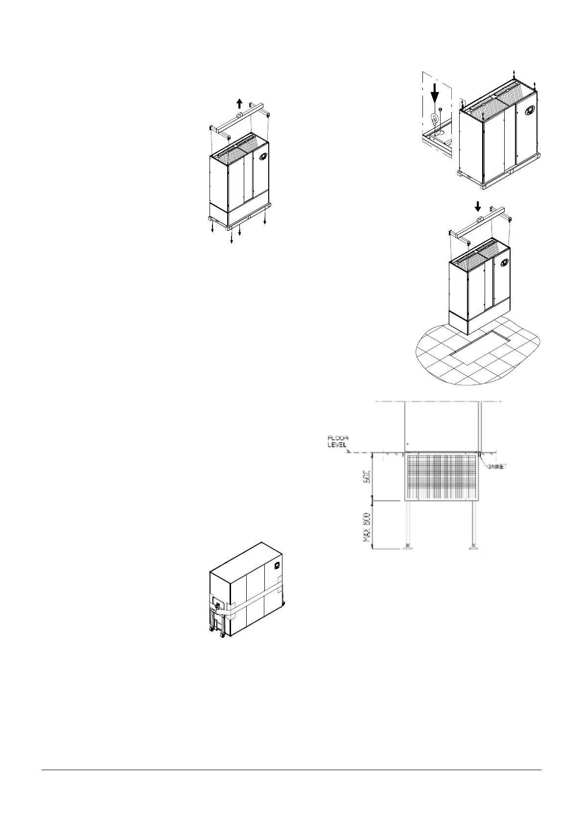
4.2 - Positioning: Downow Down.
A raised oor is required for this installation. The fan section is in-
staller completely under the oor allowing the correct airow below
the oor. See Enclosure C
1) Attach 4 shackles and M12
nuts to the coil module (not sup-
plied).
Use appropriate shackles to lift
the total assembled unit load.
2) Use sling and a 4 point lifting
bar (not supplied) to lift the unit
and place it on the oor in the
right position.
Downow Down position
Right position of the Downow Down unit respect the oor level.
All dimensions in mm
It is the responsibility of the customer to ensure the right support
below the unit; if necessary accessories are available.
See enclosure E.
NB: Seal any gap between the unit and the oor edge with a gas-
ket.