8Liebert PCW - UM - 273895 - 04.10.2018
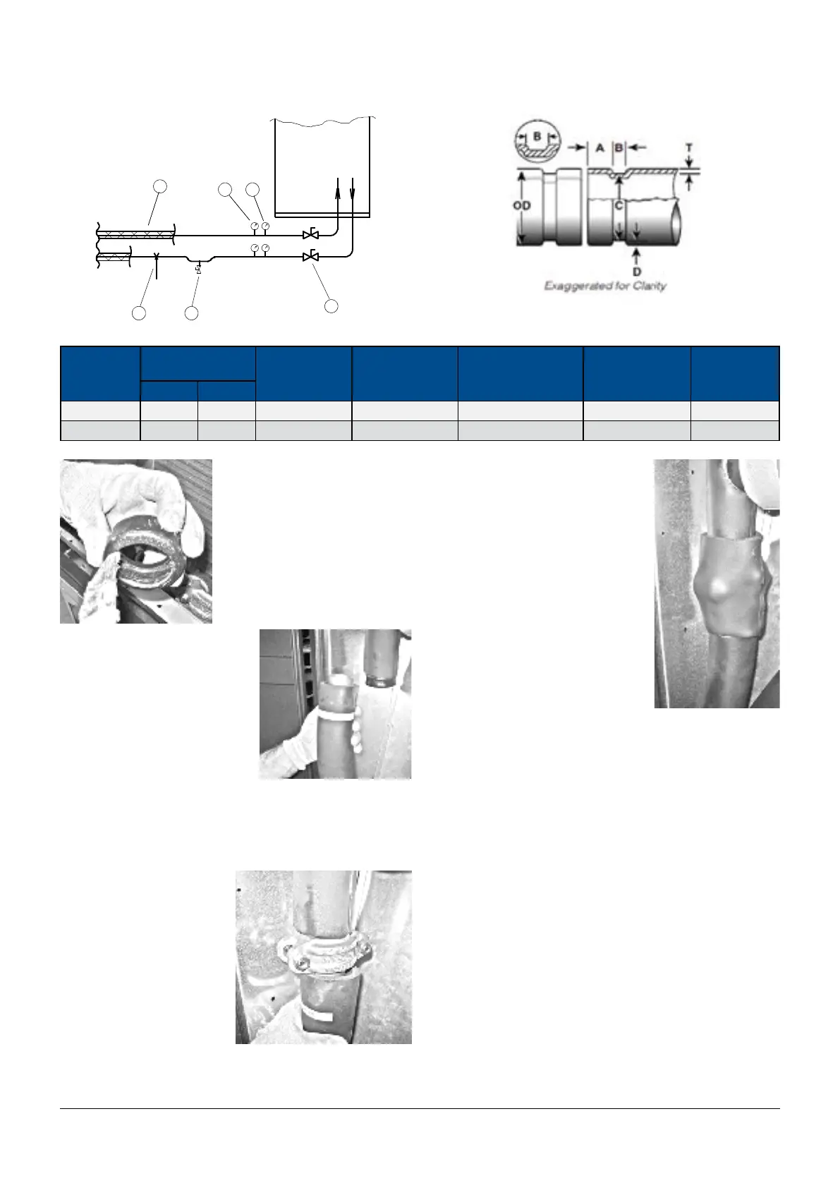
Fig. b - Chilled water circuit Fig. b1 - VICTAULIC
®
connections details.
Air
1 6
3
4 5
2
conditioner
Tab. d - VICTAULIC
®
connections details.
Nominal Size
mm
Actual Outside Dia.
mm
Gasket Seat “A”
mm
± 0.8 mm
Groove Width “B”
mm
±0.8/–.0 mm
Groove Diameter “C”
mm
+ 0/–0.5 mm
Groove Depth “D”
mm
Ref. Only
Max. Allow.
Flare Diameter
mm
Min. Max.
54 53,93 54,07 15,87 7,62 51,50 1,25 56,41
64 63,93 64,07 15,87 7,62 61,46 1,27 66,41
Installation Instructions:
1) Check tubing ends - the out-
side surface of the tubing be-
tween the groove and the tub-
ing end must be smooth and
clear; all oil, grease, dirt, and
cutting particles must be re-
moved.
2) Lubricate gasket - apply a
thin coat of Victaulic lubricant or
silicone lubricant to the gasket
lips and exterior.
3) Install gasket over one end
of the copper tubing. Make
sure the gasket lip does not
overhang the end of the copper
tubing.
4) Join tubing ends - align and bring the two copper tubing ends
together. Slide the gasket into position, and make sure it is centred
between the grooves.
NOTE: Make sure no portion of the gasket extends into the grooves
in the copper tubing.
5) Insert the housing - assem-
ble and insert the unit over the
gasket, hold the two parts of
the housing with the two bolts
loosely. Make sure the hous-
ing’s keys engage the grooves
properly on both sections of
copper tubing.
NOTE: Make sure the gasket
does not become rolled or
pinched while installing the
housing.
Failure to follow this instruc-
tion could cause damage to the gasket, resulting in joint leakage.
6) Tighten all nuts evenly by alter-
nating sides until metal to metal
contact occurs at the angle bolt
pads. Make sure the housing keys
completely engage the grooves.
Make sure the osets are equal at
the bolt pads. This is necessary to
ensure a rigid joint.
NOTE: It is important to tighten
all nuts evenly to prevent gasket
pinching.
7) Visually inspect the bolt pads at
each joint to ensure metalto-met-
al contact is achieved. Cover the
Victaulic connection with Armaex
insulation.
5.3.1 - Pipe connection Extended Height unit.
• Downow Versions with Standard Piping Bottom
• Upow Version with Standard Piping Top
Before connecting the water supplier pipes for these units it is nec-
essary to connect the two pipe stubs placed inside the unit coil
module.
Downow Versions with Standard Piping Bottom:
Connect the two pipe stubs to the piping end inside the unit.
The piping ends are located behind the unit door. The pipe with the
threaded locking ring must be connected directly to the valve outlet.
Use a gasket to join the pipe to the valve threaded connection.
Connect the second pipe stub directly to the water inlet pipe us-
ing the threaded connection or Victaulic connection. See Victaulic
Connection Details.
To facilitate the installation between the two unit modules it is pos-
sible to remove a plate on the drain panel by unscrewing 4 screws.
Remove the closer air lter to get to all the screws (see 10.4 Air
Filter check and replacement for details about Air lter removal).