5Liebert PCW - UM - 273895 - 04.10.2018
8) Lift the fan top plenum and
remove the timber pieces.
Place the plenum on the coil
module using the 4 dowels
making sure it is properly
aligned. Pay attention to the ca-
ble between the two modules.
To avoid damaging it pull the
entire cable through the coil
module.
9) Fix the two modules with the
4 hex head screws supplied (8
hex head screws for unit bigger
than PH095).
10)Mount the front and back
panel on the fan top plenum.
11) Use piano jacks to move the
unit, as described in chapter
1.7.
Place protective material be-
tween the unit and the piano
jacks and straps. If not already
done, remove 4 bolts from the
pallet, two on each side. Se-
cured to the piano jacks, the
unit can be moved to the nal
position (min. two technicians
are required).
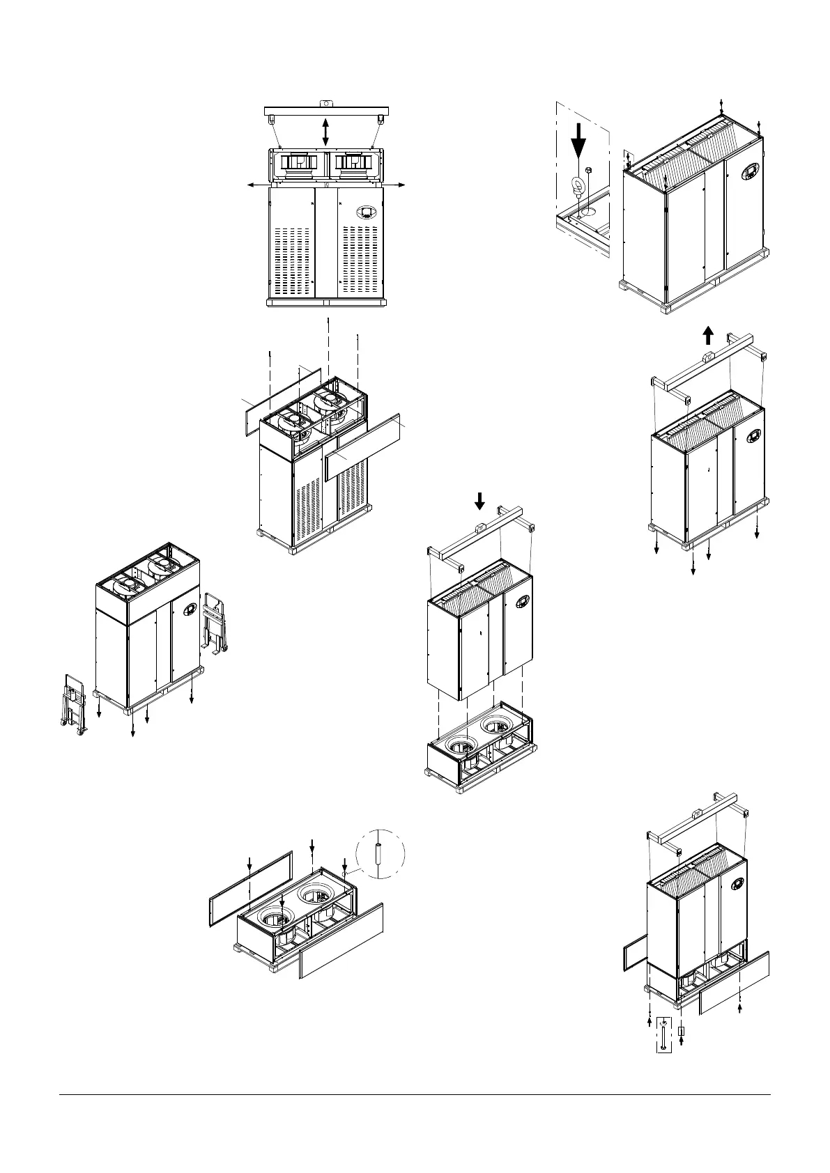
3.2 - Extended Height unit: Downow Up, Downow
Down.
1) Place the two modules (coil module and fan base module or fan
base frame) close to the nal position.
2) Remove the front and
back panels from the fan
module. Insert 4 dowels
(M8) in the upper frame.
3) Attach 4 shackles
and M12 nuts to the
coil module (not sup-
plied). Use appropriate
shackles to lift the total
assembled unit load.
4) Remove 4 bolts from the coil mod-
ule pallet, two on each side, if not al-
ready done (see chapter 1.7).
5) Use slings and a 4point lifting bar
(not supplied) to lift the coil module.
6) Place the coil module on the fan mod-
ule, using the 4 dowels making sure it is
properly aligned.
7) Fix the two modules with the 4
hex head screws supplied (8 hex
head screws for unit bigger than
PH095).
8) Run the EC Fan power cable po-
sitioned in the coil module through
the cable bushing to the fan module.
Then run the EC Fan signal cable
(and Electrical Heater cable if in-
stalled) positioned in the fan module
through the cable bushing into the
coil module. See chapter 6 for Elec-
trical connection details.