C - 2
Enclosure C - Installation drawings
Liebert PCW - UM - 273895 - 04.10.2018
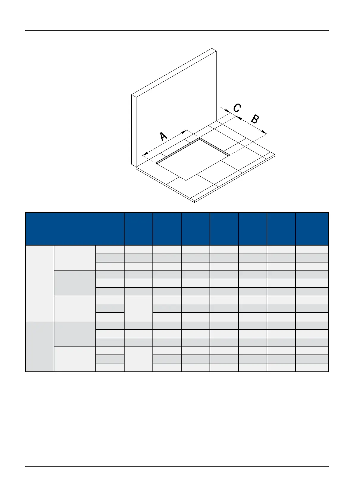
Fig. 2. Hole in the oor for Downow versions
Downow Up
Downow Down
Tab. 2 - Hole in the oor for Downow units, dimensions in mm.
Conguration Unit
PH025
PH030
PH035
PH040
PH046
PH045
PH060
PH066
PH070
PH080
PH081
PH091
PH095
PH100
PH110
PH111
PH136
PH145
PH161
PH170
PH201
Downow
Up
A 744 1100 1650 1950 2450 2850 3250
B 760 760 760 760 760 760 760
C* 70 70 70 70 70 70 70
With Base
Frame **
A 820 1176 1726 2026 2526 2926 3326
B 840 840 840 840 840 840 840
C* 30 30 30 30 30 30 30
With Legs kit **
A
NA
1156 1706 2006 2506 2906 3306
B 820 820 820 820 820 820
C* 30 30 30 30 30 30
Downow
Down
A 826 1182 1732 2032 2532 2932 3332
B 846 846 846 846 846 846 846
C* 20 20 20 20 20 20 20
With oor tiles
support kit **
A
NA
1220 1770 2070 2570 2970 3370
B 885 885 885 885 885 885
C* 50 50 50 50 50 50
* Minimal distance of the working unit from the back wall. Caution: In order to assemble and/or install accessories, a larger distance might be
required. In that case, the unit can be moved in the working position after installation / assembly procedures.
** Optional accessories - see details in Enclosures E.
NA = Not Available