Vertiv™ NetSure™ 7100 Series -48 VDC Power System User Manual
Optional LVD Driver Circuit Card
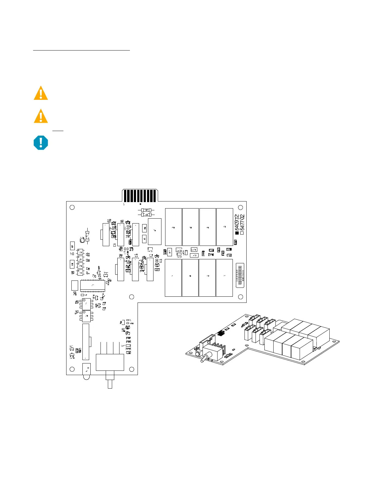
The optional LVD driver circuit card installed in the main bay contains an LVD inhibit switch and indicator. Refer to Figure 3.3. LVD
driver circuit cards are required for 2-, 3-, or 4-row distribution cabinets that contain three or more LVD contactors (LVBD and/or
LVLD); or if the distribution cabinet is equipped with an LVBD contactor rated 1200A or higher.
CAUTION! If the switch is returned to the ON (normal) position when low voltage disconnect alarms are active, a low voltage
disconnection will occur.
WARNING! While the LVD inhibit switch is in the OFF (inhibit) position, a low voltage disconnection will not occur if battery
or load voltage decreases below the low voltage disconnect setpoint. For maximum battery protection, this switch should
NOT be left in the OFF (inhibit) position.
ALERT! Do not hold the LVD inhibit switch in the up position for more than 3 seconds to avoid damaging the contactor.
Figure 3.3 Optional LVD Driver Circuit Card
LVD Inhibit Switch
Momentary UP / Middle / Down
Momentary UP Position: Closes all LVD Contactors (inhibit mode).
Middle Position: OFF (Controller DOES NOT control LVD’s) (inhibit mode).
DOWN Position: ON (Controller controls LVD’s).
LVD Inhibit
Active Indicator
Illuminates when the
low voltage disconnect
circuit has been disabled
through the use of the
LVD Inhibit switch.
J6 J5 J4
J3 J2 J1
J9
J7
S1
Note: The UP position will not close the LVBD contactor
if the battery is man
ually disconnected using the
Manual Battery Disconnect Switch.
Switch and indicator located
on circuit card installed in
Main Bay only.
Main Bay

 Loading...


