Vertiv™ NetSure™ 7100 Series -48 VDC Power System User Manual
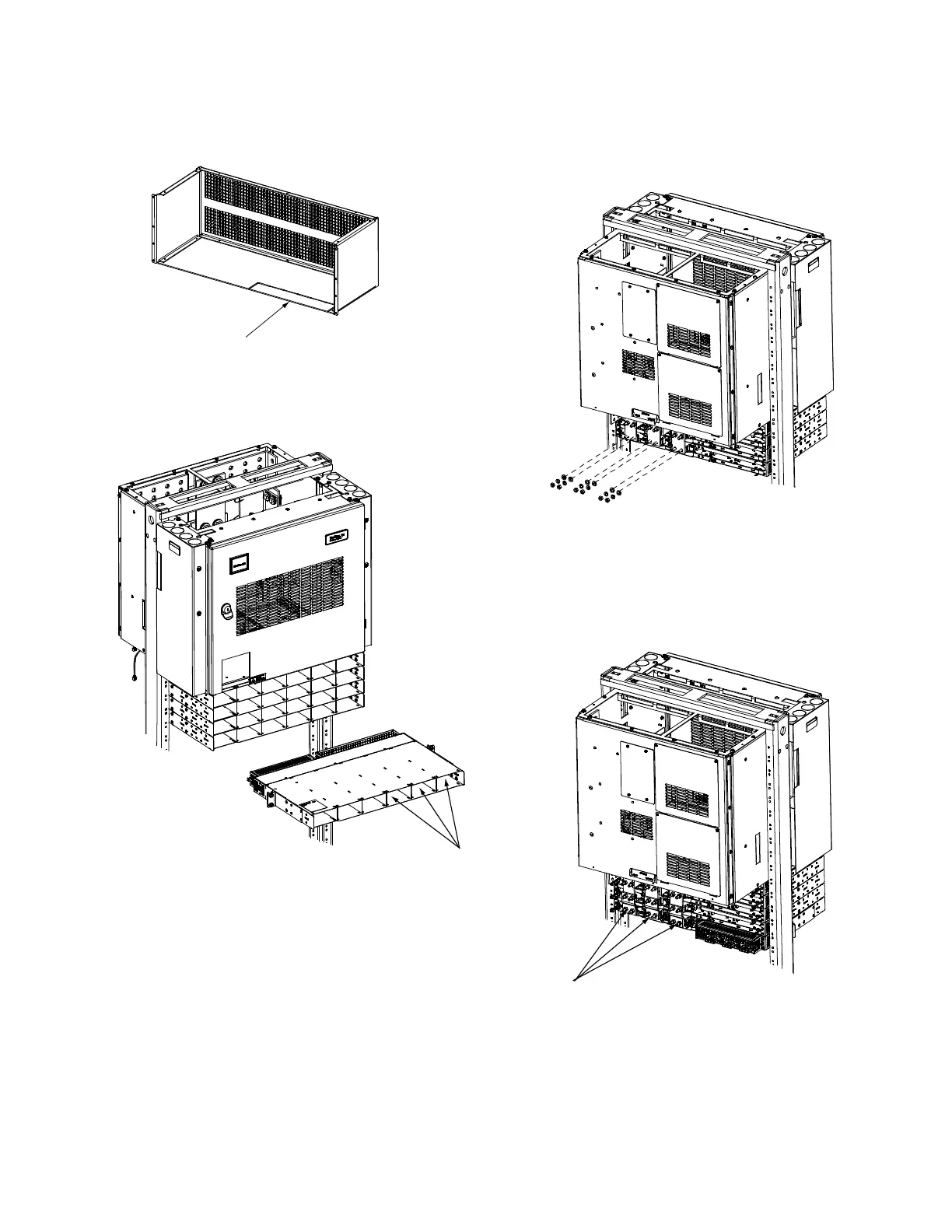
Figure 4.7 Installing a Field Expansion Module Mounting Assembly Spec. No. 588705300
1. Remove busbar rear shield from
existing rectifier/converter shelves.
Remove the cut-out panel
from the busbar rear shield.
3. Install the expansion module
mounting shelf into the rack.
4. Remove busbar rear shield from
expansion module mounting shelf.
5. Install the busbars provided
with the expansion module
mounting shelf between the
shelves. Torque to 60 in-lbs.
6. Re-install the rear busbar
shields previously removed.
Front
Rear
Busbar Rear Shield
Cut-Out Panel
Rear
Apply +24V or -58V label to right
three converter slots of the expansion shelf
based on the converter output voltage.
2. Remove hardware from the
lowest module mounting shelf’s
-48V, return, and +24V or -58V
(if present) busbars.

 Loading...


