Vertiv™ NetSure™ 7100 Series -48 VDC Power System User Manual
Replacing a Bullet Nose Fuseholder
Procedure
NOTE!
Refer to Figure 5.2 as this procedure is performed.
1. Open the distribution cabinet’s front door by turning the latch in the counterclockwise position (system’s in a relay rack), or
open the system’s enclosure door.
2. Remove the fuse carrier from the mounted fuseholder body by pulling it straight out. Hold the fuseholder body while you pull
the fuse carrier from the body.
3. Gently rock the defective fuseholder up and down while pulling firmly outward until the fuseholder is free from the
distribution panel.
4. Orient the fuseholder as shown in Figure 5.2. Insert the terminals on the rear of the fuseholder into their corresponding
sockets on the distribution panel. Ensure the alarm contact on the back of the fuseholder makes contact with the alarm
terminal on the spring strip. Push fuseholder in firmly until fully seated in the distribution panel.
5. Push the fuse carrier securely back into the mounted fuseholder body. Note that a polarizing key on the bottom of the
carrier prevents the carrier from being inserted upside down.
6. Verify no Fuse Alarms are active.
7. Close the distribution cabinet’s front door and turn the latch clockwise to secure the door (system’s in a relay rack), or close
the system’s enclosure door.
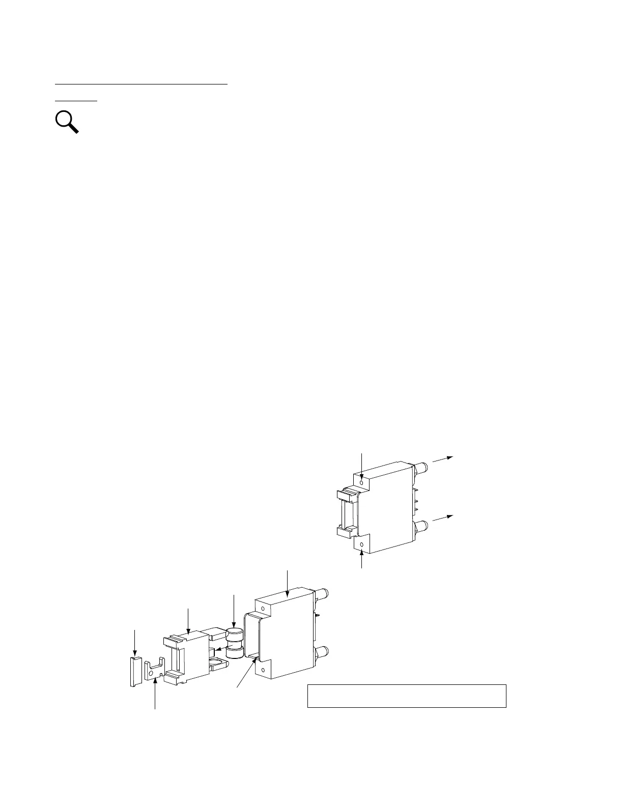
Figure 5.2 Replacing a TPS/TLS Fuseholder and/or Fuse
Fuseholder Asse
mbly
Longer Side
to the Bottom
Shorter Side
to the Top
Fuse Ca
rrier
Fuseholder B
ody
TPS/TLS Fuse
Polarizing Keyway
Matches Key on
Bottom of Fuse Carrier
Fuseholder Assembl
y
Exploded View
Fusehold
er Assembly (P/N 117201) includes
bod
y & carr
ier, alarm f
use, and alarm fuse sa
fety cover
.
In
ser
t these terminals
in
to
corresponding sockets
on distribut
ion
panel.
GMT-X
Safety Fuse Cover
(Replacement
P/N 248898700)
GMT-18/100A
Alarm Fuse
(Replacement
P/N 248610301)

 Loading...


