Chapter 1 Product Introduction
RDU501 Intelligent Monitoring Unit User Manual
1
2
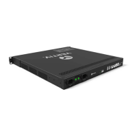
1. Break-away detection indicator 1-8 2. Digital / analog input 1-8
Figure 1-4 EXP8DOAO card
The port definition of the EXP8DOAO card is shown in Table 1-12.
Table 1-12 Definitions of the ports of the EXP8DOAO card
Digital or analog output 1 to 8
RJ45 port
DO/AO1 to DO/AO8
Digital output: normally open contact +
normally closed contact
Analog output: 0 to 10V
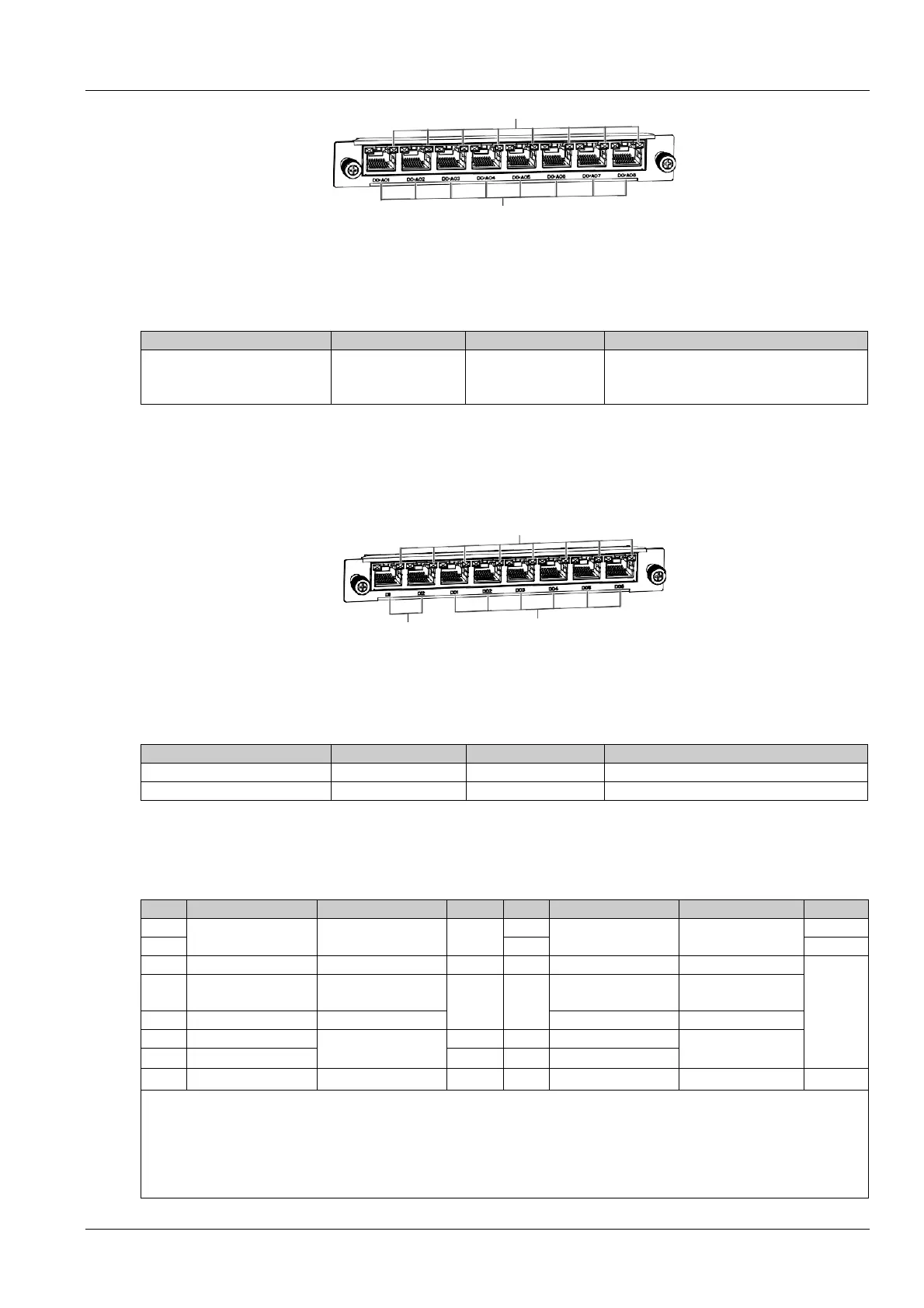
EXP2DI6DO card (optional)
The EXP2DI6DO card provides two digital inputs and six digital output ports. For the DI and DO line sequences, refer
to the DI/Smoke and DO line sequences in Table 1-14, but the DO is not energized. Any one of the digital inputs can
be linked to the 6-way digital output hardware. Its appearance is shown in Figure 1-5.
1
2
3
1. Break-away detection indicator 1-8 2. Digital input 1-2 3. Digital output 1-6
Figure 1-5 EXP2DI6DO card
The port definition of the EXP2DI6DO card is shown in Table 1-13.
Table 1-13 Definitions of the ports of the EXP2DI6DO card
Digital input potential-free dry contact
Digital output potential-free dry contact
Line sequence definition of RDU501 and expansion card
The definition of RDU501 and expansion card line sequence is shown in Table 1-14.
Table 1-14 Definitions of the RDU501 and expansion card line sequence
12V 12V 12V
0 to 10V 12V
NC
4
detection
detection
GND
GND
detection
detection
DI
DI
+
+
-
-
1. The line sequence of the RJ45 port is arranged as a notch downward, 1 to 8 from left to right;
2. D+ and D- are two levels of the RS485 differential signal;
3. NC: Not Connected;
4. The DI and DO line sequence of the EXP2DI6DO card refers to the line sequence of DI/Smoke and DO;
5. The close and open of the DO sampling signal in the RDU501 software uses the normally open contact 6 (normally open)
 Loading...