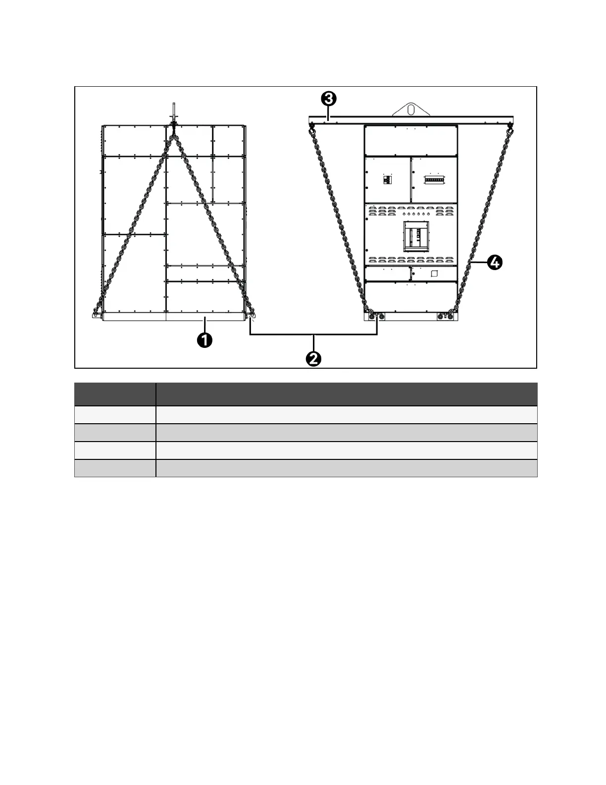
Figure 3.6 Lifting with Lifting Eye, Chains, and Spreader
Item Description
1 Skid plinth
2 Skid plinth lifting eye
3 Spreader bar
4 Chain or Strap
Non traditional lifting means
1. If necessary, laid the panel on its side or back. Additional plinths will need to support and protect the switchgear
structure, as well as add lifting points to the corresponding surface.
2. Mount the plinths onto the rear and/or side like the standard plinths, fitted to the base of the panel. Depending
on the surface size of the side or rear, additional supports may need to be installed.
3. Remove the skins from either the rear or side to install the plinths. Mount the plinths into the frame using M8
hardware as noted on the drawings. Hardware should be torqued based on Table 7.1 on page43 .
4. Once the plinths are installed, then panel movements can be completed by a qualified movement team based on
specific project MOP.
5. When the panel is in the designated location remove the additional plinths and put back the skin in place.
18 Proprietary and Confidential ©2024 Vertiv Group Corp. 3 Packaging and Handling
Vertiv™ UL891 Switchboard Installer/User Guide