VESDA
®
LaserPLUS Installation Manual
Version 1.5 9
Note: For LaserPLUS detectors mounted in the Inverted Orientation position, the
display and/or programmer modules have to be rotated 180°. Refer to
Section 6.4 for procedure to rotate the modules. The position of the
Programmer and Display modules can be interchanged.
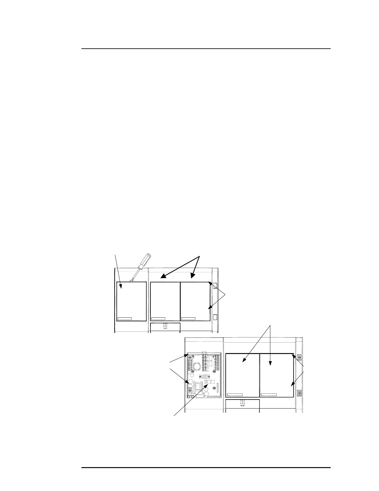
6.2 Removal of Front Cover
(a) Insert a 4mm x 1mm flat blade screwdriver (A) into notch. Refer to Figure 4.
(b) Gently open the blank plate (B) with the screwdriver.
(c) Lift out the two screw covers (C) with a flat blade screwdriver.
(d) Use a Philips head screwdriver and remove the four retaining screws (D). Screws are
captive and are retained within the front cover. Refer to Figure 4.
(e) When the front cover is opened, there are two plastic straps joining the cover to the
enclosure.
(f) If the front cover is to be separated from the enclosure do the following:-
i) On the rear of the front cover or on the enclosure side, twist the plastic strap 90°
and slip strap out through slot.
ii) Locate the cable loom that connects the central processor card to the back of a
display or programmer module that is located on the front cover. On the back of
the programmer or display module, disconnect this cable connector from its
socket (labelled Term) if present.
Note:
Mark this connector and socket before removing if you are unsure
of the wiring.
Figure 4 Removing the Blank Plate, Screw Covers, Retaining Screws, Programmer and
Display Modules.
Termination Card
Screws (D)
Screws (D)
Display, Programmer or
Blank Plate Location
Blank Plate
C