LaserPLUS Installation Manual VESDA
®
14 Version 1.5
6.11 Termination Card Details
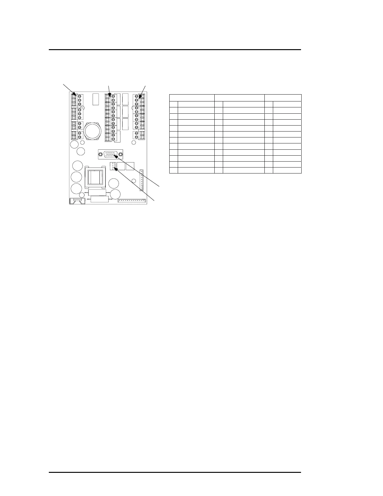
Figure 9 Termination Card Details for 7 Relays
6.12 Procedure to Terminate Wires to the Termination Card
Use the appropriate local wiring standards or use the following suggested procedure
listed below. Check Sections 6.13, 6.14 and 6.15 for specific information on terminal
connections.
(a) Strip off 5 to 7mm (0.2 to 0.3in) of outer insulation from each wire.
(b) For multi-stranded wire only - Twist wire strands together.
(c) On the termination card, remove the plugs from its terminal sockets.
(d) Insert the correct wires into the terminal plugs.
(e) Tighten terminal plug screw.
(f) Repeat steps (c) to (e) as required.
(g) Insert plugs into the correct sockets on the termination card.
(h) Check the wires are attached to its terminals.
(i) Ensure no bare wires are exposed at the terminals. The wire insulation must touch
the terminal plugs at the pin connection opening.
(j) Check the terminations are correct by referring to the appropriate circuit diagrams in
Sections 6.13, 6.14 and 6.15.
Terminal A Terminal B Terminal C
Pin 1
Pin 11
Pin 1 Pin 1
Pin 10
Pin 12
VESDAnet
Terminal A Terminal B Terminal C
1 VESDAnet A+ 1 Isolate (NO) 1 Fire 2 (NC)
2 VESDAnet A- 2 Isolate (C) 2 Fire 2 (C)
3 Shield 3 Isolate (NC) 3 Fire 2 (NO)
4 VESDAnet B+ 4 Minor Fault (NO) 4 Fire 1 (NC)
5 VESDAnet B- 5 Minor Fault (C) 5 Fire 1 (C)
6 Shield 6 Minor Fault (NC) 6 Fire 1 (NO)
7 Power (+) 7 Urgent Fault (NO) 7 Action (NC)
8 Power (-) 8 Urgent Fault (C) 8 Action (C)
9 Power (+) 9 Urgent Fault (NC) 9 Action (NO)
10 Power (-) 10 Alert (NO) 10 GPI -
11 Alert (C) 11 GPI +
12 Alert (NC)
GPI = General Purpose Input
FOK LED
Connector
 Loading...