LaserPLUS Installation Manual VESDA
®
12 Version 1.5
6.7 Securing the Mounting Bracket
Warning: Make sure that there are no electrical wires or plumbing behind the
mounting position before drilling. Ensure the mounting position is flat.
a) Remove the drilling template from the centre page of this manual.
b) Determine the orientation for the detector (Normal or Inverted Orientation). Place the
drilling template onto its mounting location in the correct orientation and drill out the
appropriate holes. Refer to the drilling template for orientation.
c) Use the appropriate fasteners to suit the mounting surface. Secure the bracket to the
surface.
6.8 Attaching the Detector onto the Bracket
(a) Determine the required orientation for the LaserPLUS. Refer to Figure 3 for
orientation.
(b) Place the three bridges located on the rear of the detector onto the three lances
located on the mounting bracket. Refer to Figure 8.
(c) Push the detector downwards until it locks onto the lances and engages the fitting
dimples.
(d) Check the unit does not slip off its bracket.
(e) To remove, push the detector upwards and pull away from wall.
(f) To prevent unwanted removal of the detector, insert screws into the keyhole slot at
location shown on template and tighten screw. Drill out these holes before mounting
the detector onto its mounting bracket by using the mounting template to locate the
screw hole position. Insert at least one screw through the key hole slots located in the
Termination Card compartment.
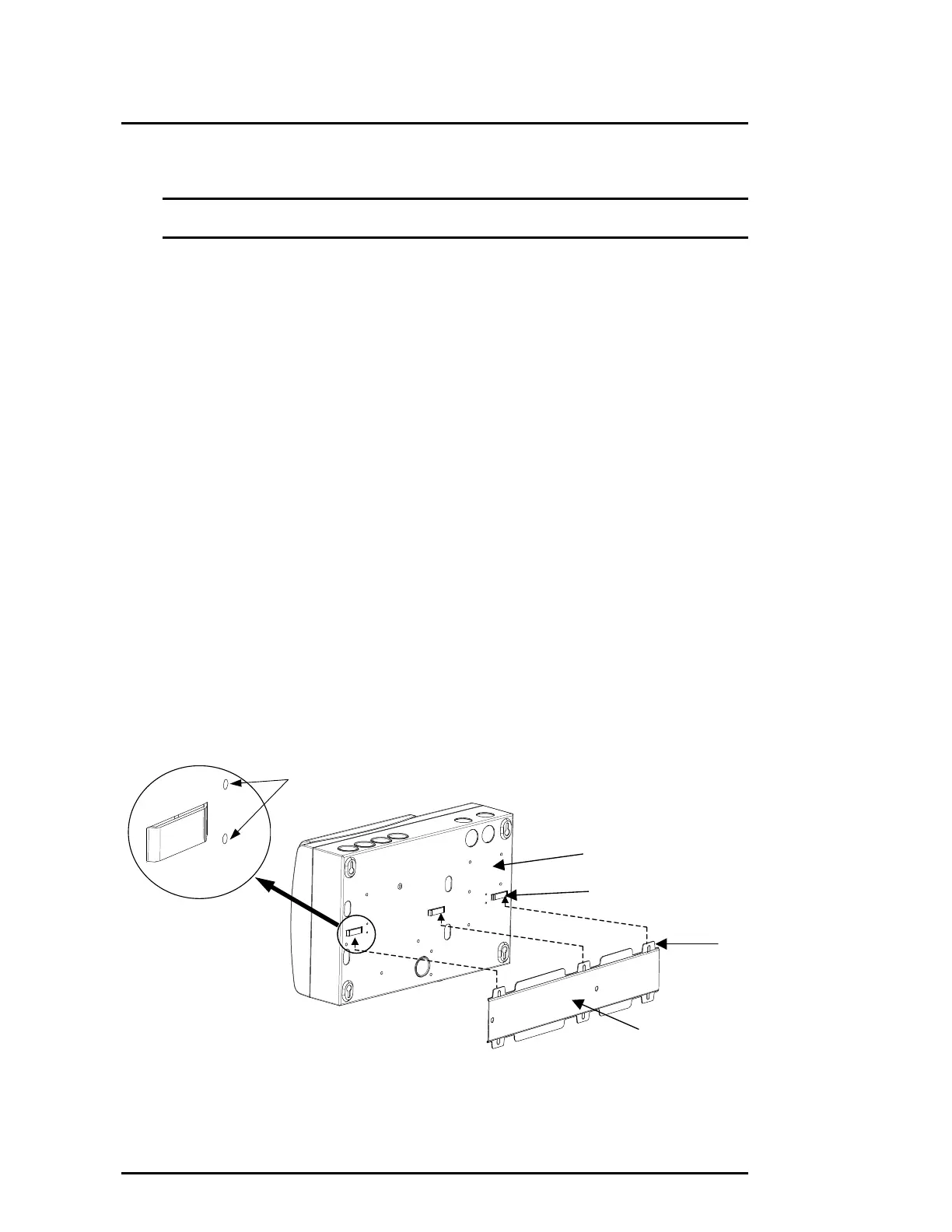
Figure 8 Mounting the Detector onto the Mounting Bracket
Mounting Bracket
Rear of Detector
Bridge
Lance
Fitting Dimples
 Loading...