VESDA
®
LaserPLUS Installation Manual
Version 1.5 19
8. Preliminary System Checks
Perform the following preliminary system Setup and checks before commissioning.
(a) Logging onto the system with a PC or a LCD Programmer. See Section 8.1.
(b) VESDAnet communication checks. See section 8.2
(c) Normalise the airflow. See section 8.3
(d) Basic pass/fail smoke test. See section 8.4
8.1 Logging On to the System
Check with your distributor for the default User Levels and PIN numbers to log on to the
system. Fault code 25 or 26 is generated when a LCD Programmer or a PC-Link HLI
device is connected to the VESDAnet socket. This fault clears when the programming
device is disconnected from the detector.
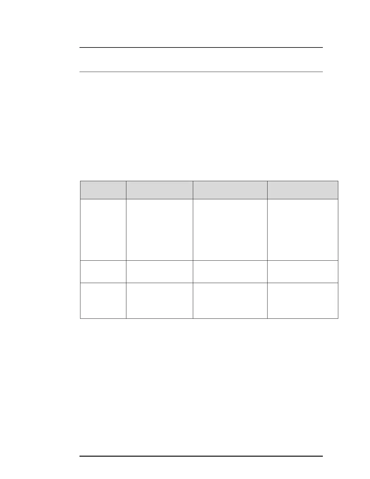
Procedure
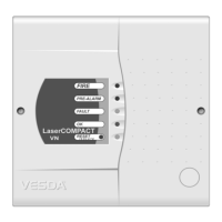
LCD Programmer
Module
Hand Held LCD
Programmer
PC Programmer
Connecting the
programming
device to a
Detector or to a
VESDAnet
socket.
No physical connection
required
Plug the LCD Programmer
cable into the VESDAnet
socket on the Termination
card or to a remote
terminal. Refer to Figure 5
for location of the
VESDAnet socket on the
Termination Card.
Connect the PC via a
PC-Link HLI device to
the VESDAnet socket on
the Termination Card or
to a remote terminal.
Refer to Figure 5 for
location of the VESDAnet
socket on the
Termination Card.
Logging onto
the system.
Press any programmer
key to display the
Logon screen.
Press any programmer
key to display the Logon
screen.
Run VConfig Basic or
VConfig Pro program
from the PC.
Enter your
Access Level
and PIN
Number.
Use the Programmer
keys to enter your
access level and PIN
number. Press ↵ when
completed.
Use the Programmer keys
to enter your access level
and PIN number. Press ↵
when completed.
Enter your Access Level
and PIN Number when
the Logon screen
appears.
8.2 VESDAnet Communication Check
Note: This test verifies the VESDAnet system is functioning correctly and all devices
connected on VESDAnet are communicating. Write down the VESDAnet number
for each detector, programmer and display module. The location of the
VESDAnet number for the detector is shown in Figure 5. The programmer and
display modules have this number located at the bottom left hand side of the front
face.
If any of the listed VESDAnet numbers and devices are incorrect, check the
VESDAnet wiring to all devices.
 Loading...