VESDA VESDA Maintenance Guide
www.xtralis.com 21
Removal Procedure
Save configuration and isolate the detector
1. Using Xtralis VSC, make a connection to the detector.
2. Select FILE > SAVE. Provide a configuration file name and select SAVE.
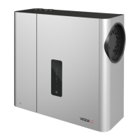
3. Isolate the detector by pressing the ISOLATE button (1) or isolate from within Xtralis VSC.
4. Using a flat bladed screw driver, disengage the clips and open the front panel cover plate and screw
covers (2). Remove the screws (3).
Figure 8-5: Remove Front Cover
Note: Refer to the Xtralis VSC online help for information on using the software.
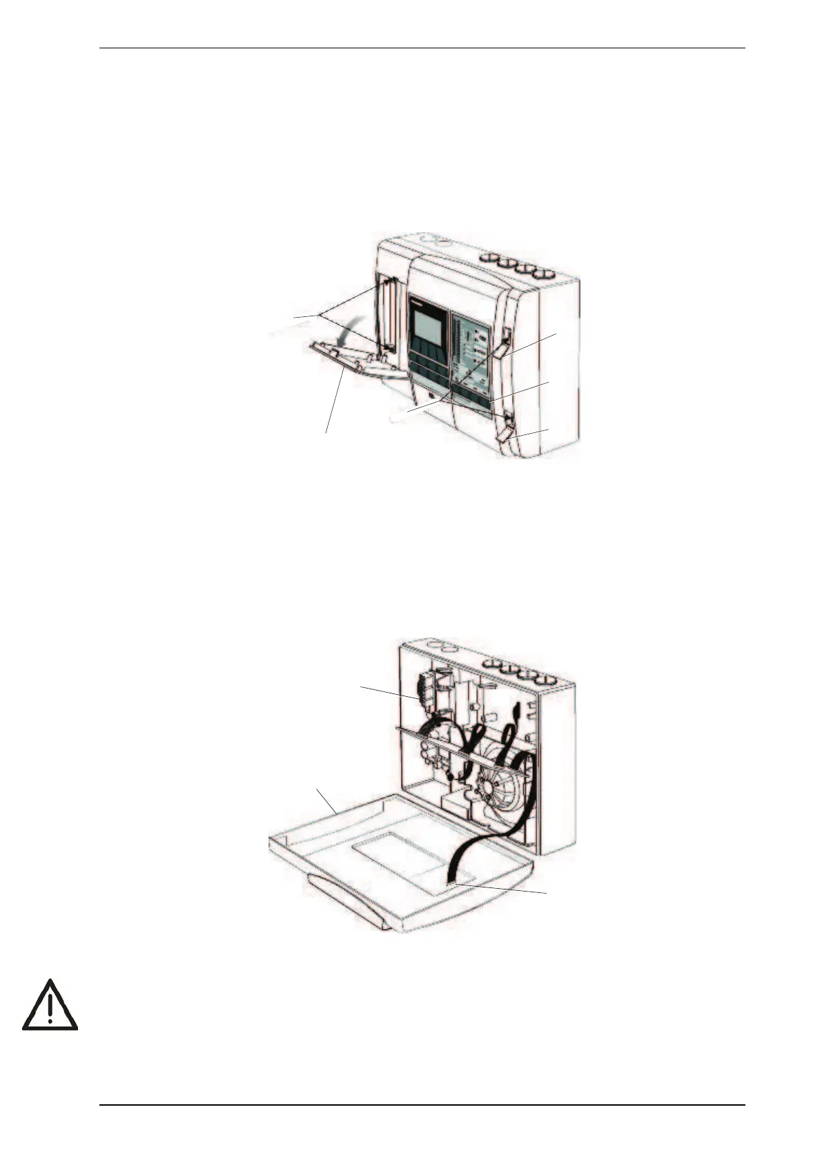
Open the detector and disconnect cables
1. Open the front panel (4).
2. Disconnect the power supply cables (5) from the detector termination card.
3. Disconnect the two chassis/manifold wiring connectors connected to the termination card.
4. Disconnect the head processor card cable connector (6) from the front panel if Display or Programmer
modules are fitted.
Figure 8-6: Open Front Cover
Caution: Disconnect the power supply cables before plugging/unplugging connections to the termination
card or processor cards. Failure to do so may cause data corruption and/or component failure.