VESDA Maintenance Guide VESDA
22 www.xtralis.com
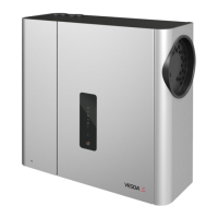
Remove the chassis
1. Unscrew the processor card retaining screw (7).
2. Disengage the processor card (8) from the retaining clips (9) and turn sideways (as shown) to gain access
to the cable connectors.
3. Disconnect the flow sensor cable connector (10) and scanner motor connector (VESDA VLS only) (11)
from the processor card.
4. Unscrew the chassis retaining screws (12).
5. Using a flat blade screw driver, disengage the chassis retaining clips (13) from the detector housing and
remove the chassis assembly (14).
7
12
8
13
13
VSP-006-NEN
14
9
10
11
Figure 8-7: Remove the chassis
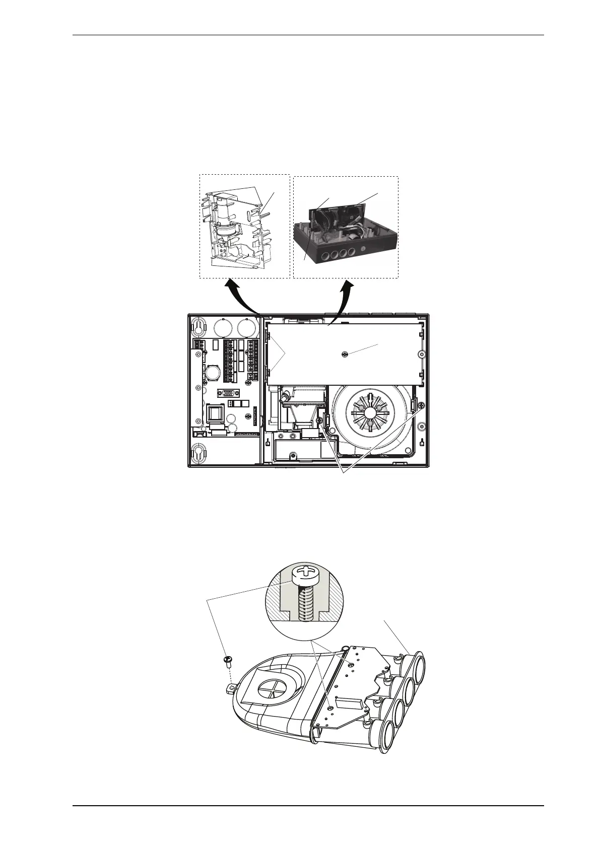
Remove the manifold
1. Unscrew the manifold retaining screws (14).
2. Unscrew the manifold assembly (15).
Figure 8-8: Remove the manifold