VESDA Maintenance Guide VESDA
24 www.xtralis.com
Notes:
l Ensure that the flow sensor connector (5) is securely connected.
l Gently support the upper part (6) of the flow sensor cable while installing the chassis assembly (7) and
ensure there is no slack in the lower part (8) of the flow sensor cable. A slack on the lower part of the cable
will prevent correct alignment of the chassis assembly, which may cause air leaks.
l Ensure that the retaining clips (9) (four places) are correctly seated.
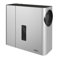
Secure the processor card
1. Position the processor card with the right hand side of the board aligned to the retaining clips (16) as
shown (B).
2. Gently push down on the left hand side of the board as shown (C) until the retaining clips (17) lock the
processor card into the correct position.
3. Install the cardboard cover (18) of the processor card.
Figure 8-11: Secure the processor card
Note:
l Ensure that the wiring cables connected to the processor card (15) are correctly routed. Incorrect routing
of the wiring cables will prevent correct installation of the processor card.
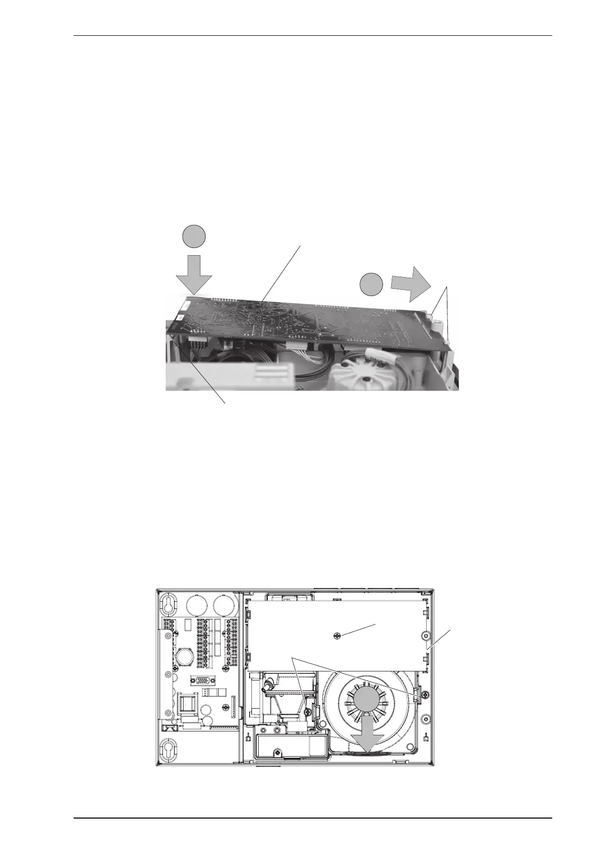
Align the manifold with the aspirator
1. Tighten the processor card retaining screw (19).
2. Tighten the chassis assembly retaining screws (20).
3. Connect the two chassis/manifold wiring connectors to the termination card.
4. Gently press on the bottom area of the chassis/manifold assembly (D) to make sure that the manifold is
aligned with the aspirator.
Figure 8-12: Align the manifold with the aspirator