VESDA VESDA Maintenance Guide
www.xtralis.com 25
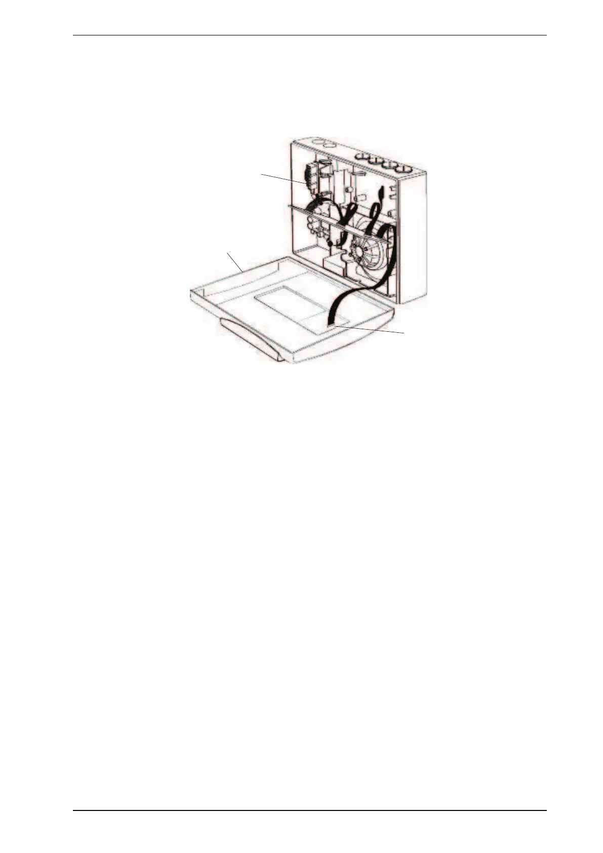
Connect cables and install the front panel
1. Connect the head processor card connector (21) to the front panel (22) if Display or Programmer modules
are fitted.
2. Connect the power supply cables (23) to the detector termination card.
3. Install the front panel to the detector housing. Install and tighten the front panel retaining screws. Install
the front panel cover plate and screw covers.
Figure 8-13: Connect cables and install the front panel
4. Using the LCD Programmer or Xtralis VSC, restore the configuration and re-commission. Refer to the
following documents available at www.xtralis.com.
l VESDA Commissioning Guide # 10195
l VESDA LCD Programmer Product Guide # 10194
8.1.4 Replacing VESDA VLP and VESDA VLS Termination Cards
Note: Disconnect the detector power supply before commencing replacement of the termination card.
Only reconnect the 24 VDC power supply once the replacement termination card is secured.
Replacement Procedure
1. Mark out the wire positions on each terminal socket before removing them.
2. Remove all terminal plugs (C) from sockets, leaving the wires attached to the plugs, refer to Figure 8-14
below.
3. Remove the 10 wire and 13 wire cable looms from their socket (B) in Figure 8-14 below.
4. Remove the five Phillips head screws (A) in Figure 8-14 below.
5. Remove the termination card.
6. Attach the Termination Card with five Phillips head screws (A).
7. Reattach the 10 wire and 13 wire cable looms to the sockets (B). The connectors can only be inserted into
the socket one way. Turn the connector around if the connector does not fit into its socket.
8. Reconnect the terminal plugs to their sockets, ensuring the plugs are connected to their correct socket
(C).