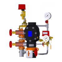
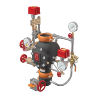
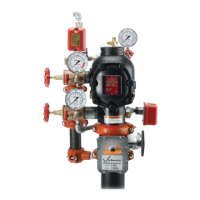
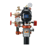
EXTERNAL INSPECTION
WARNING
• The building owner or their representative is responsible for
maintaining the fire protection system in proper operating
condition.
• To ensure proper system operation, valves must be inspected
in accordance with current national standards or in accordance
with the requirements of the local authority having jurisdiction
(whichever is more stringent). Always refer to the instructions in
this manual for additional inspection and testing requirements.
• The frequency of inspections must be increased in the presence
of contaminated water supplies, corrosive/scaling water supplies,
and corrosive atmospheres.
• Depressurize and drain the piping system before attempting to
install, remove, adjust, or maintain any Victaulic products.
Failure to follow these instructions could cause system failure,
resulting in death, serious personal injury, and property damage.
NOTICE
• Any activities that require taking the valve out of service may
eliminate the fire protection provided.
• Consideration of a fire patrol should be given for the affected
areas.
• Before servicing or testing the system, notify the authority
having jurisdiction.
WEEKLY INSPECTION
1. Perform a visual inspection on the valve and trim on a weekly
basis. NOTE: If the alarm valve is equipped with a low-pressure
alarm, monthly inspections may be sufficient. Contact the local
authority having jurisdiction for specific requirements.
MONTHLY INSPECTION
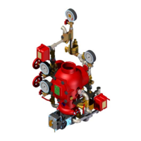
1. Record the system pressure (14) and water supply pressure (5).
It is normal for system water pressure to be higher than the water
supply pressure due to the alarm check valve trapping pressure
surges above the clapper. Confirm that the water supply pres-
sure is within the range of normal pressures observed in the area.
Significant loss of water supply pressure could indicate an adverse
condition in the water supply.
2. Inspect the valve and trim for mechanical damage and corrosion.
Replace any damaged or corroded parts.
3. Confirm that the alarm check valve and trim are located in an area
that is not subject to freezing temperatures.
4. If the valve is installed in a variable pressure system, confirm that
no excessive leakage is occurring from the restricted orifice/alarm
line drain. It is normal for some leakage because pressure surges
lift the clapper and allow water into the intermediate chamber.
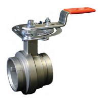
5. Confirm that all valves are in their normal operating positions (refer
to table below).
Valve Normal Operating Position
Alarm Line Ball Valve Open (Lockable)
Water Supply Main Control Valve Open
System Main Drain Valve Closed
System Test Valve Closed
I-751.VDS / Series 751 FireLock
™
European Alarm Check Valve Stations / Installation, Maintenance, and Testing Manual
I-751.VDS_9REV_F
 Loading...

