INSTALLING THE COVER PLATE GASKET AND COVER PLATE
CAUTION
• Use only Victaulic-supplied replacement parts.
Failure to follow this instruction could cause improper valve opera-
tion, resulting in property damage.
1. Verify that the cover plate gasket is in good condition. If the gasket
is torn or worn, replace it with a new, Victaulic-supplied gasket.
2. Align the holes of the cover plate gasket with the holes in the cover
plate.
3. Insert one cover plate bolt through the cover plate and cover plate
gasket to ease alignment.
CAUTION
• DO NOT over-tighten the cover plate bolts.
Failure to follow this instruction could cause damage to the cover
plate gasket, resulting in valve leakage.
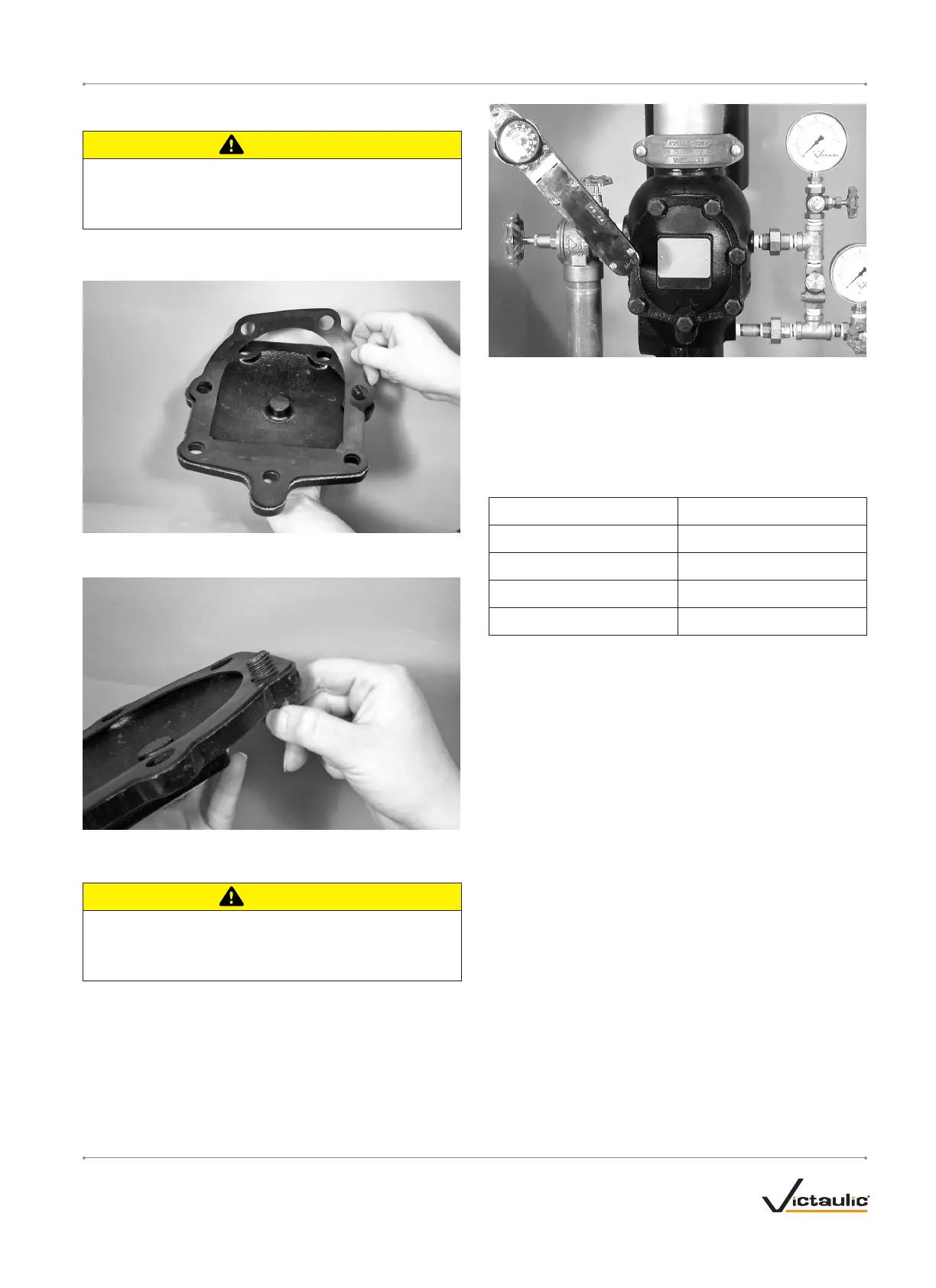
4. Align the cover plate/cover plate gasket to the valve. Make sure the
clapper spring’s arms are rotated to their installed position. Tighten
all cover plate bolts into the cover plate/valve body.
4a. Torque all cover plate bolts in an even, crossing pattern. Refer
to the “Required Cover Plate Bolt Torques” table below for the
required torque values. DO NOT over-tighten the cover plate bolts.
REQUIRED COVER PLATE BOLT TORQUES
Size Torque N•m
DN80
81
DN100
136
DN150
156
DN200
136
5. Place the system back in service by following the “Placing the
System in Service” section.
I-751.VDS / Series 751 FireLock
™
European Alarm Check Valve Stations / Installation, Maintenance, and Testing Manual
I-751.VDS_19REV_F

 Loading...