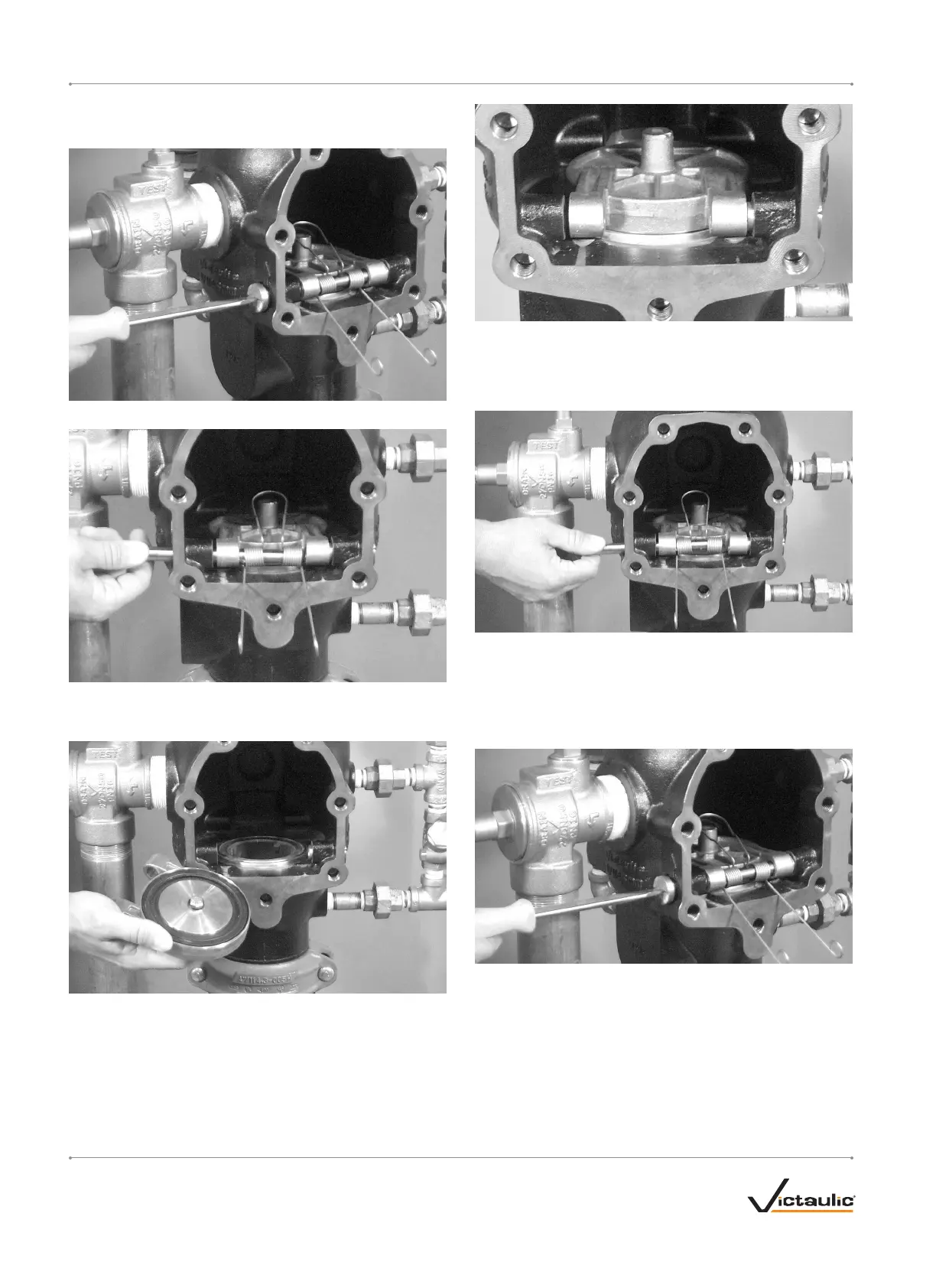
REMOVING AND REPLACING THE CLAPPER ASSEMBLY (ALL SIZES)
1. Perform steps 1 – 4 of the "Required Internal Inspection" section.
2. Remove one clapper shaft retaining bushing from the valve body.
3. Remove the clapper shaft. NOTE: As the shaft is being removed,
the clapper spring will drop out of position. Keep the clapper
spring for re-installation.
3a. Remove the clapper from the valve body.
4. Verify that the clapper seal is installed properly in the clapper by
referring to the applicable “Removing and Replacing the Clapper
Seal” section. Place the new clapper assembly onto the valve-body
seat ring. Make sure the holes in the clapper arms align with the
holes in thevalve body.
5. Insert the clapper shaft halfway into the valve body.
5a. Install the clapper spring onto the clapper shaft. Make sure the
loop of the clapper spring is facing toward the clapper, as shown
above.
5b. Finish inserting the clapper shaft through the clapper arm and
valve body.
6. Apply thread sealant to the clapper shaft retaining bushing. Install
the clapper shaft retaining bushing into the valve body until hand-
tight.
6a. Tighten the clapper shaft retaining bushing until metal-to-metal
contact occurs with the valve body.
7. Check the clapper for freedom of movement.
8. Replace the cover plate by following the "Installing the Cover Plate
Gasket and Cover Plate" section.
9. Place the system back in service by following the "Placing the
System in Service" section.
I-751.VDS / Series 751 FireLock
™
European Alarm Check Valve Stations / Installation, Maintenance, and Testing Manual
I-751.VDS_18 REV_F

 Loading...