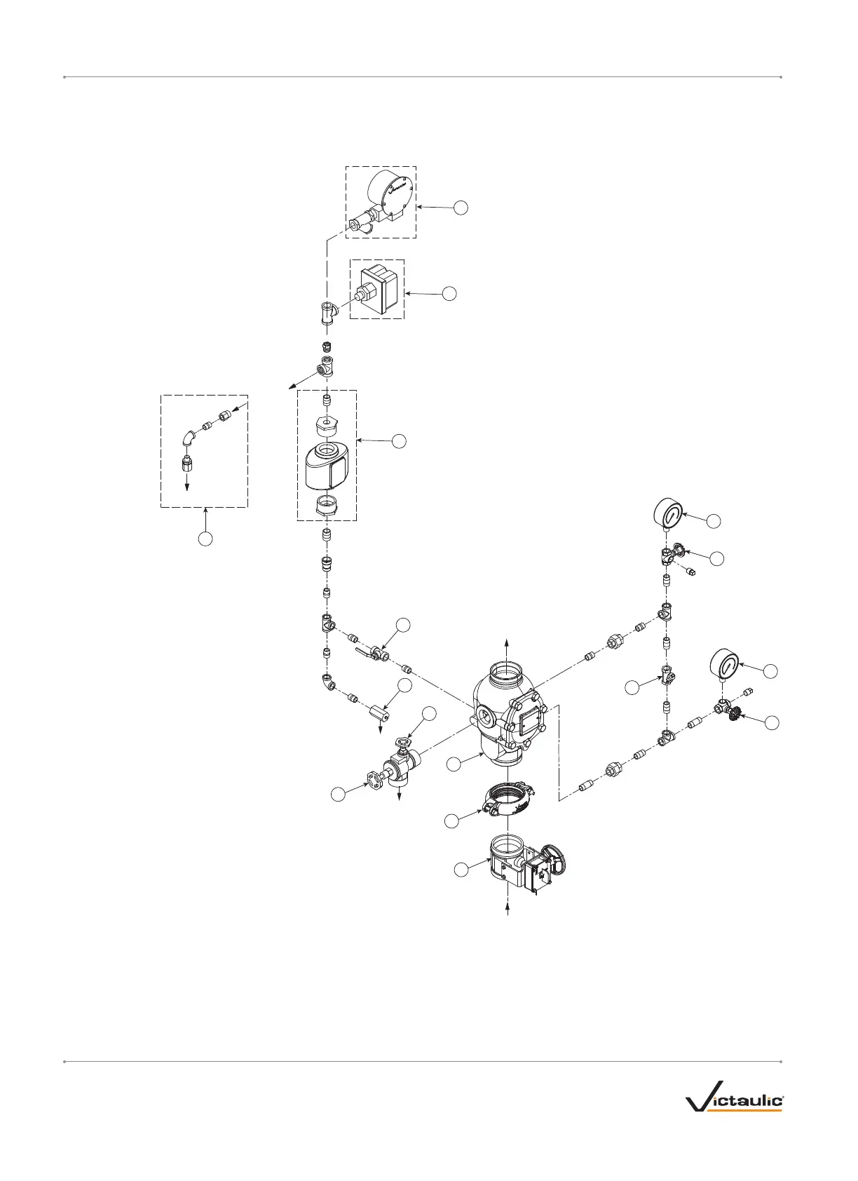
EXPLODED VIEW DRAWING – TRIM COMPONENTS
SERIES 751 FIRELOCK EUROPEAN ALARM CHECK VALVE STATIONS
(OPTIONAL ACCESSORIES ALSO SHOWN)
Optional Series 752V
Retard Vent Kit
To Water Motor
Alarm or Optional
Series 752V Retard
Vent Kit
Pipe to
Open Drain
10
9
15
12
From Water
Supply
To
System
To
Drain
To
Drain
3
2
5
14
4
4
1
11
7
8
Normally
Open
(Lockable)
6
13
Bill of Materials
1 Series 751 FireLock European Alarm
Check Valve
2 FireLock Rigid Coupling
3 Water Supply Main Control Valve
4 Gauge Valve
5 Water Supply Pressure Gauge (0-25 Bar)
6 Drain Swing Check Valve
7 Restricted Orifice/Alarm Line Drain
8 System Main Drain Valve
9 Series 752 VdS Retarding Chamber
Assembly (Optional/Sold Separately)
10 Alarm Pressure Switch
11 Alarm Line Ball Valve
(Lockable - Normally Open)
12 Series 760 European Water Motor Alarm
Assembly (Optional/Sold Separately)
13 System Test Valve
14 System Pressure Gauge (0-25 Bar)
15 Series 752V Retard Vent Kit *
(Optional/Sold Separately)
* The Series 752V Retard Vent Kit is required any time an
air break is needed above the Series 752 VdS Retarding
Chamber Assembly. In addition, the Series 752V Retard
Vent Kit is required if multiple valves are tied into one water
motor alarm and a check valve isolates each line.
I-751.VDS / Series 751 FireLock
™
European Alarm Check Valve Stations / Installation, Maintenance, and Testing Manual
I-751.VDS_4 REV_F
 Loading...


