INTRODUCTION
The following instructions are a guide for proper installation of Victaulic Series 751 FireLock European Alarm Check Valve Stations. These instructions
involve pipe that is prepared and grooved properly in accordance with Victaulic specifications.
NOTICE
• Drawings and/or pictures in this manual may be exaggerated for clarity.
• This product and this installation, maintenance, and testing manual contain trademarks, copyrights, and/or patented features that are the
exclusive property of Victaulic.
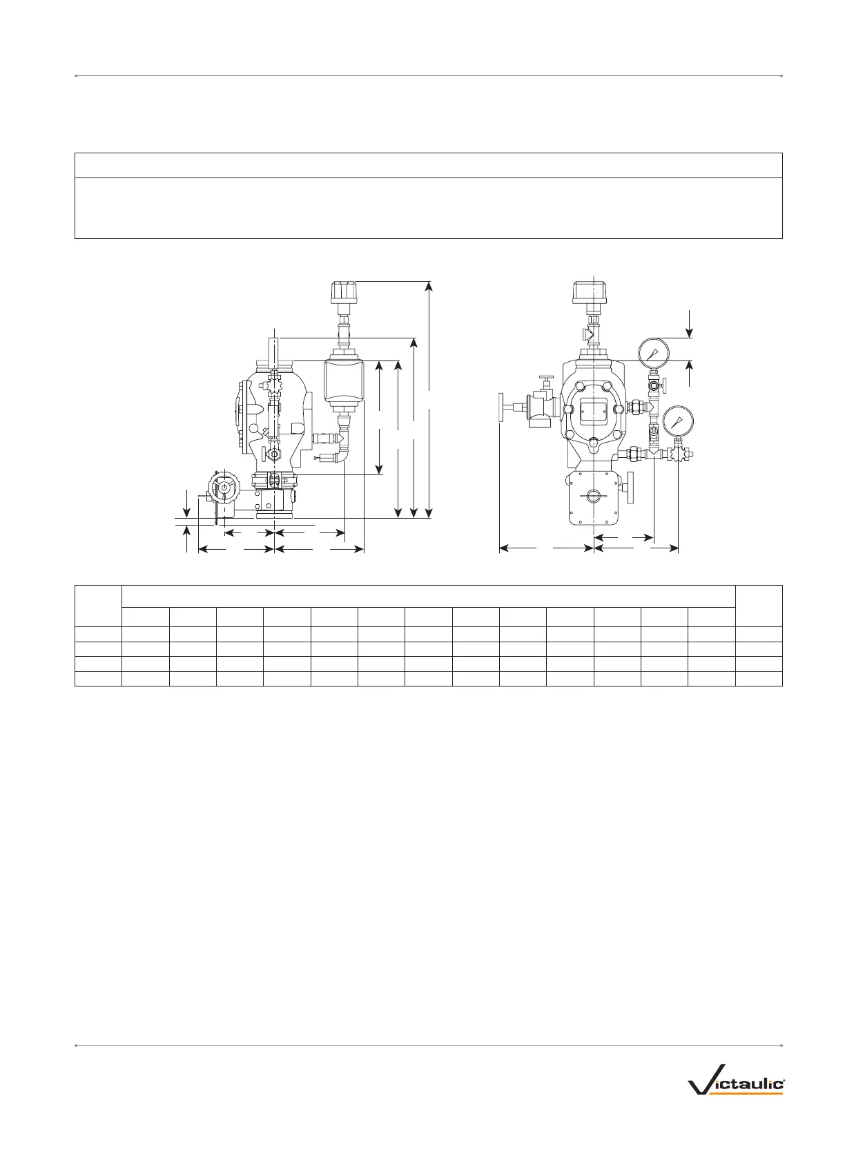
TRIM DIMENSIONS
C D
H
A
A
1
B
1
B
G
K
Size
Dimensions – centimeters
Approx.
Weight
Each
kilogramsA* A1 B B1 C D E F G H I J K
DN80 32.03 42.24 — 71.86 14.48 21.21 22.11 27. 5 6 4.67 18.64 26.93 27.97 — 24.0
DN100 38.18 50.66 57. 88 75.97 16.13 22.33 24.45 26.68 2.14 19.33 27.14 30.37 7. 22 54.0
DN150 40.64 56.32 64.44 79.38 18.60 25.77 26.93 31.79 — 20.30 28 .11 31.08 8.12 69.0
DN200 44.45 58.65 — 85.80 16.66 28.34 26.81 34.39 — 23.85 30.87 34.56 — 83.0
* The “A” dimension is the measurement from the top of the valve body to the bottom of the valve body (takeout dimension).
NOTE: Overall height “B” is the greatest height if the optional Series 752 VdS Retard Chamber Assembly is not installed.
I-751.VDS / Series 751 FireLock
™
European Alarm Check Valve Stations / Installation, Maintenance, and Testing Manual
I-751.VDS_3REV_F
 Loading...


