It is recommended to install the balance tankas close to the bath as possible. Thus pipe of the 110 mm diameter
for transporting water from the bath gutter to the tank may be short. A sewage system connection of 50 mm
diameter should be prepared at the place of future installation of the balance tank(tank emergency overflow).
If the balance tankis to be installed near the bath, one of the dimensions of the bathroom must be increased.
Note: A free access to the top and the water level measuring system of the balance tankmust
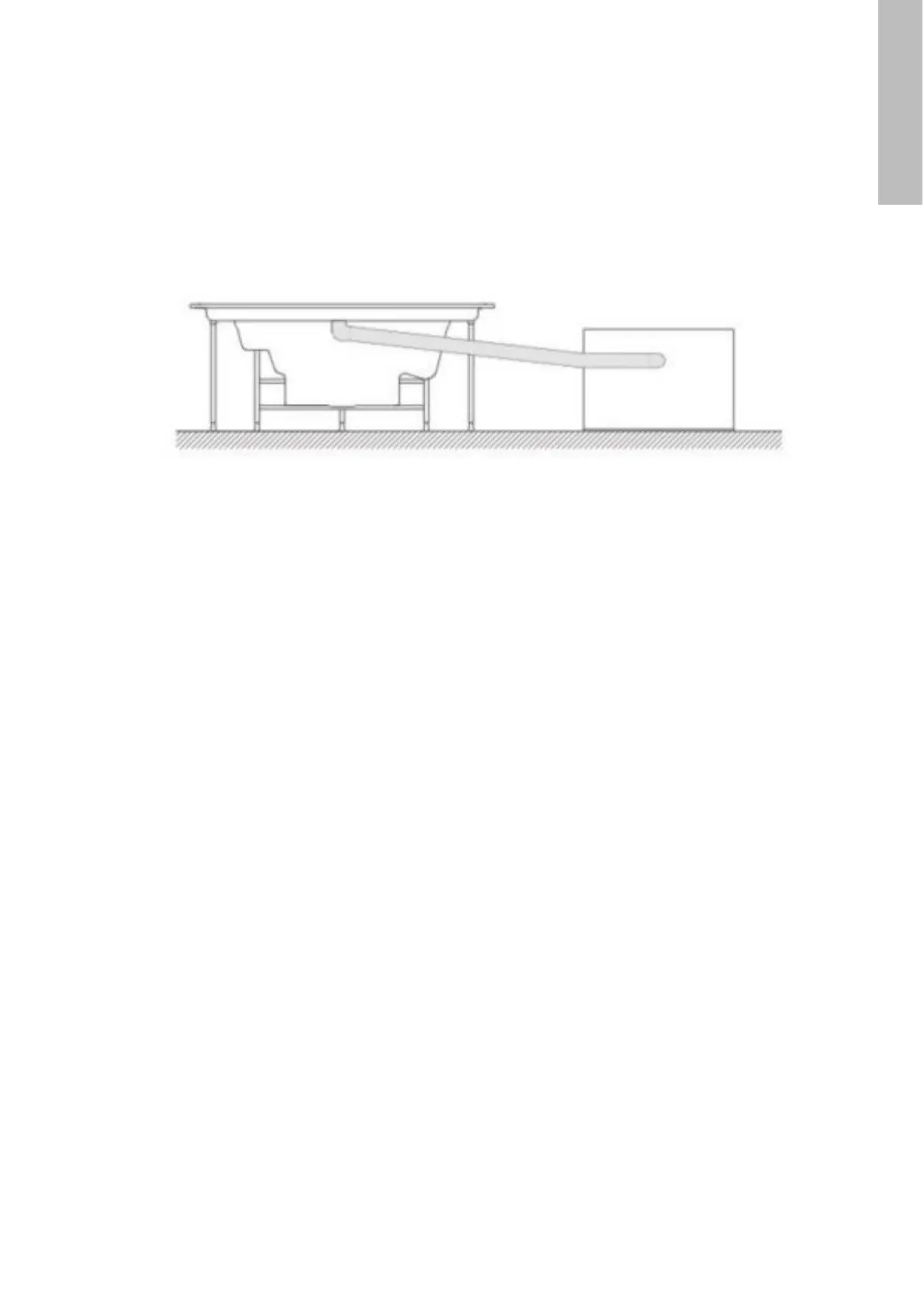
be provided because of periodical cleaning. Balance tankshould be situated in such a way that
there is a gravitational water flow from overflow gutter to balance tank(outlet from overflow
gutter should be located above balance tank– see the figure below).
If a system of automatic chemicals feeding is installed (it is required for public objects) a small room
(1.20 x 1.20 m) should be prepared for a chlorinator. It should be provided with an individual ventilating
system. A chemicals storage should be built, too
The room must be ventilated to provide fresh air to the equipment (cooling of pump driving engines, air for air
massage, cooling of control boxes and contactors) and to ensure its long life. Mechanical pressure and exhaust
ventilation system with an inlet grate and exhaust fan are recommended.
The machine room must be provided with a floor drain and a sewage system connection of 75 mm diameter.
The floor drain is used to remove water from the machine room floor (in case of maintenance work or a
breakdown).
If the sewage plumb line is situated above the floor, a 50 x 50 x 50 cm gully must be constructed, whereas a pump
provided with a floating sensor and connected with the sewage system should be installed there. A standard
filtering system has been designed to enable emptying the system and cleaning the sand filter with the filtering
pump, so the sewage terminal of the 75 mm diameter may be located above the machine room floor level.
2
Appropriate 400 V 3~ power supply should be provided in the machine room using a cable 5 x 4 mm through a
differential current breaker 25 A / FHASE located on a bracket of the machine room - Spa bath with a 9 kW
heater. If aheat exchanger is used Appropriate 400 V 3~ power supply should be provided in the machine room
2
using a cable 5 x 4 mm through a differential current breaker 16 A located on a bracket of the machine room.
Maximum power consumption of Spa bath with a 9 kW heater is 13 kW, including heat exchanger 4 kW.
If a heat exchanger is to be used, pipes of 1" diameter supplying and draining working medium to the building
heating system should be connected to the room assigned for the machine room. The pipes should be ended
with straight-run cut-off valves and the system should also include a circulating pump CO (recommended
3
capacity 12 m / h).
Example of correct connection of bath and equalising tank
21
ENGLISH