PAGE 7 of 40 GSM DOOR INTERCOM TECHNICAL MANUAL VER 2.0.8
EXTENSION BUTTON MODULES
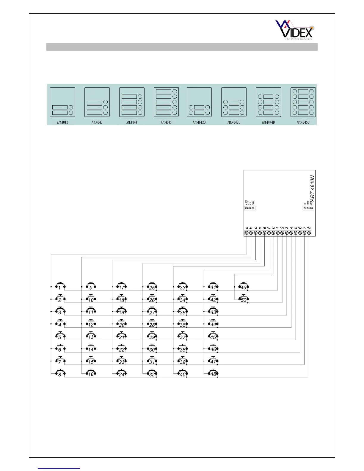
The GSM intercom module will accept up to 50 call buttons. Any of the standard 4000
series button modules can be used as shown below (Button 1 is in the bottom right corner
counting up).
Button connections to the GSM module are shown below. (Note: For clarity power and
other connections are not shown below). Also take care when using additional button
modules with intercom modules which also have buttons. For example, an intercom
module with one button means the extension button modules must begin from button 2, an
intercom module with 2 buttons means the extension module must begin from button 3.
Button module notes:
If the GSM module has 1 button, the additional button module buttons should be addressed beginning with 2 (i.e. The first
button of the button module should be connected between a & 2, the next between a & 3 etc)
If the GSM module has 2 buttons, the additional button module buttons should be addressed beginning with 3 (i.e. The first
button of the button module should be connected between a & 3, the next between a & 4 etc)
If the GSM module has 4 buttons, the additional button module buttons should be addressed beginning with 5 (i.e. The first
button of the button module should be connected between a & 5, the next between a & 6 etc)
1

 Loading...