67009600-EN - Edition 2015 - Rev. 1.0
68
VX2300 Digital System - “2 Wire” Audio/Video Door Entry System
VX2300 Digital System - Installation handbook
Art.2305 Extension Relay for VX2300 digital systems
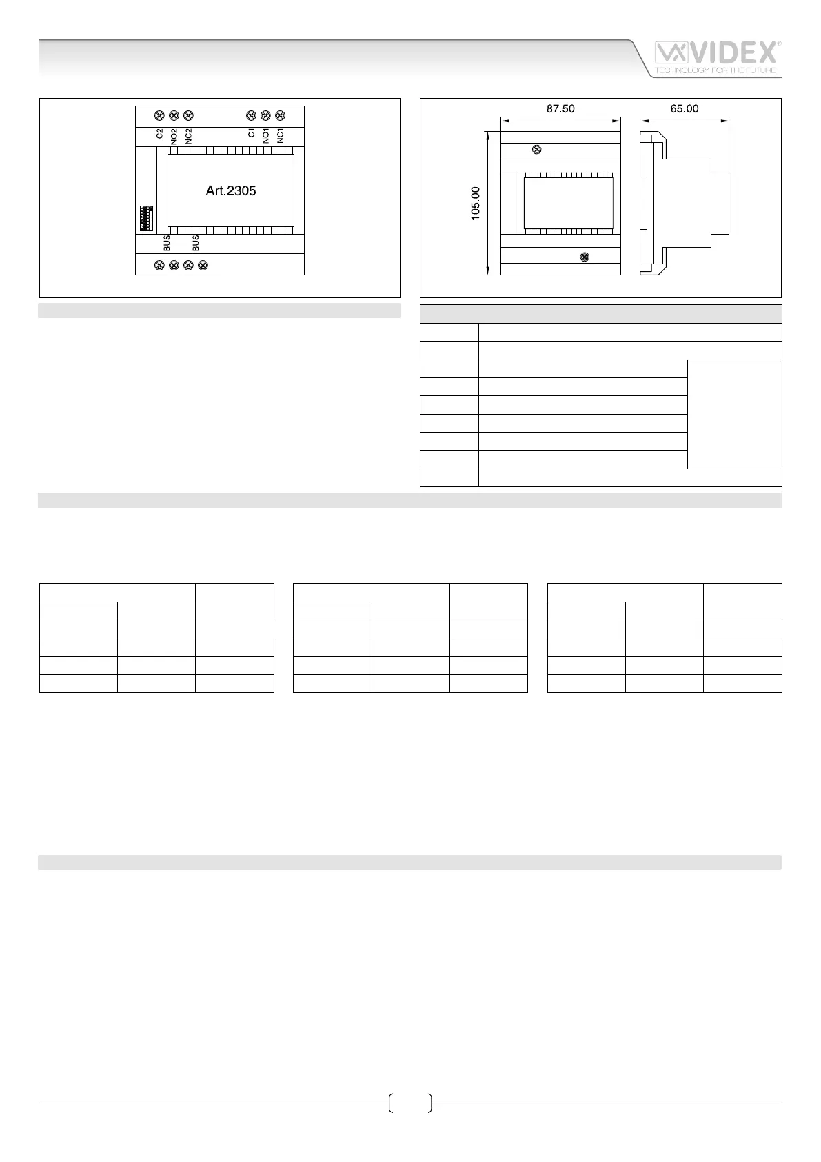
Fig. 1
Fig. 2
DESCRIPTION
This unit can be connected directly to the bus and has two
operating modes: general purpose extension relay and
apartment extension relay for additional sounders. As general
purpose extension relay, the built-in relays are controlled by
the relevant button of the intercom or videophone while as
extension sounder relay, relay one will operate on each ring and
relay two will operate for the duration of the call.
CONNECTION TERMINALS & DIPSWITCHES
BUS Input/Output bus connection terminals
BUS Input/Output bus connection terminals
C2 Relay 2 common contact
Max
24Vac/dc 5A
NO2 Relay 2 normally open contact
NC2 Relay 2 normally closed contact
C1 Relay 1 common contact
NO1 Relay 1 normally open contact
NC1 Relay 1 normally closed contact
DIPSW 8 way dip-switch to set the relay operating mode
PROGRAMMING
The operating mode is set by switch 8 as shown below. Note: After making changes to the dip-switch settings it is necessary to
disconnect it from the bus (or power the system down) and then reconnect before the changes will take aect.
GENERAL PURPOSE EXTENSION RELAY SWITCH 8 = OFF
When the unit is set as general purpose extension relay, switches 1 to 6 are used to set the relays addresses and activation times.
Switches Relay 1,2
Addresses
1 2
OFF OFF 1,2
ON OFF 3,4
OFF ON 5,6
ON ON 7,8
Switches Relay 1
time
3 4
OFF OFF 2 seconds
ON OFF 4 seconds
OFF ON 16 seconds
ON ON 32 seconds
Switches Relay 2
time
5 6
OFF OFF 2 seconds
ON OFF 4 seconds
OFF ON 16 seconds
ON ON 32 seconds
Switch 7 is not used.
For example if switch 1 is set to ON and switch 2 is set to OFF (addresses 3 & 4), pressing the “dot” button on the intercom (or “double
dot” on the videophone) 3 times will operate relay one while pressing 4 times will operate relay two.
EXTENSION SOUNDER RELAY SWITCH 8 = ON
When the unit is set in this mode, switches from 1 to 7 (8 is not used but set to on) are used to set the address of the unit: the address
of the unit is set to the same address as the videophone or intercom it that apartment (refer to intercom/videophone SW1 settings).
When the apartment is called, relay 1 will operate 4 times (once for each ring) while relay 2 will energise for the duration of the call
(Approx. 60 seconds). The relays revert to the de-energised state if the call is cancelled or the user ends the call.
SPECIFICATION
Housing/Mounting: 5 Module A Type DIN box / DIN bar or directly to the wall
Push Buttons: N/A
Programming: Yes, carried out by the 8 way dip-switch
Controls: N/A
Power Supply: from the bus
Working Temperature: -10 +50°C
Dry contacts relay: Max 24Vac/dc 5A
 Loading...


