VX2300 2 Wire Video Digital System
PrtCode:VX2300_2_9.doc – Pag.9 08/03/2011 Rev.2.9
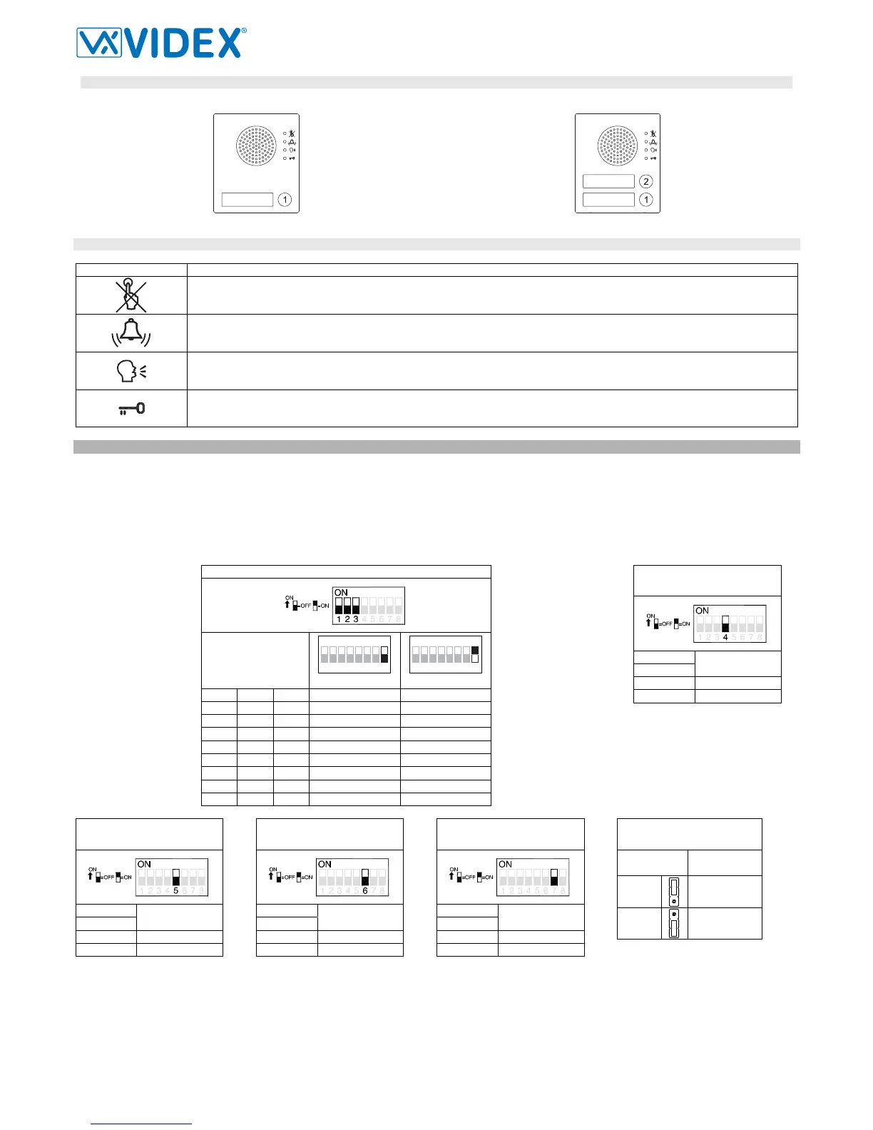
BUTTONS LAYOUT
As factory preset, built-in buttons are configured to call address 1 or 1 & 2 but the setup may be changed by altering the position of the 3 wires
shown in figure 2 with reference “m”.
Art.4303N-1 Art.4303N-2
FRONT LEDS SIGNALLING DESCRIPTION
Symbol Description
When illuminated, indicates that it is not possible to make a call because a call or a conversation is in progress (from the out-
door station from which you are calling or from another outdoor station on systems with multiple entrances). The LED will be
off when the system is in stand-by
If illuminated, indicates that the call from the outdoor station is in progress. The LED will switch OFF when the call is an-
swered or after the programmed number of rings.
If illuminated, indicates that it is possible to speak because the call has been answered. The LED will switch OFF at the end
of a conversation (or at the end of the conversation time).
If illuminated, indicates that the door lock has been released. It will switch OFF at the end of the programmed “door opening”
time.
PROGRAMMING
The programming consists of the following settings:
- Unit ID (1..8);
- Door Opening Time (2 or 6 seconds);
- Conversation Time (1 or 2 minutes);
- Buttons Matrix start address (1 or 65);
- Default Camera (4330N or External);
- Door Open Relay operating mode (capacitor discharge or dry contacts).
First 5 settings are carried out through the first 7 switches of the 8 way dip-switch (reference j on figure 2) while the 6
th
setting is carried out through the
jumper (reference h on figure 2) both accessible from the rear side of the module.
Unit ID
Switches
Position
4
5
3
2
1
876
ON
8 = OFF
4
5
3
2
1
876
ON
8 = ON
1 2 3 ID ID
OFF OFF OFF 1 9
ON OFF OFF 2 10
OFF ON OFF 3 11
ON ON OFF 4 12
OFF OFF ON 5 13
ON OFF ON 6 14
OFF ON ON 7 15
ON ON ON 8 16
Door Opening Time
Switches
Seconds
4
OFF 2
ON 6
Conversation Time
Switches
Minutes
5
OFF 1
ON 2
Matrix Button
Start Address
Switches
Start
Address
6
OFF 1
ON 65
*Main Camera
Switches
Main Camera
7
OFF 4330N
ON External
Door Open Relay
Operating Mode
Jumper
Position
Operating
Mode
Upper
Dry contacts
Lower
Capacitor **
Discharge
* This setting, when the door station includes the camera module 4330N and a second external camera, establishes which camera is the main camera
from which the video signal will come from at the beginning of the call. The video signal can be switched to the secondary camera at any time by press-
ing the specific button on the videophone or videomonitor.
** When set as capacitor discharge, connect the electric lock between terminals “GND” and “NO”.