100
■
Flue gas temperature sensor
■
Flow temperature sensor
■
Cylinder temperature sensor
■
Outlet temperature sensor
■
Temperature sensor, low loss header
■
Outside temperature sensor
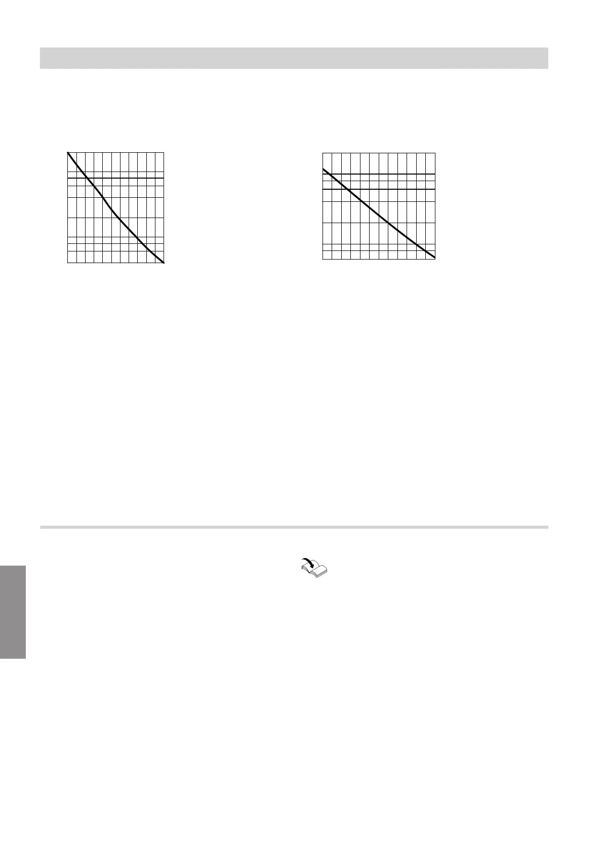
10
1
10 30 50 70 90 110
Temperature in °C
0.4
0.6
0.8
2
4
6
8
20
Resistance in kΩ
Sensor type: NTC 10 k
Ω
100
10
-20 -10 0 10 20 30
Temperature in °C
6
8
20
40
60
80
200
Resistance in kΩ
Sensor type: NTC 10 k
Ω
Fault during commissioning (fault message F.416)
During commissioning, the control unit checks for cor-
rect placement of the flue gas temperature sensor. If
fault message F.416 is displayed:
1. Check whether the flue gas temperature sensor is
correctly installed (bayonet fitting). See previous
diagram.
2. If required, correct the position of the flue gas tem-
perature sensor.
3. Check the flue gas temperature sensor resistance.
See previous chapter. Replace faulty flue gas tem-
perature sensor if required.
4. Turn off the ON/OFF switch.
5. Turn the ON/OFF switch back on.
Restart the commissioning assistant.
6. Check for leaks on the flue gas side.
Note
If fault message F.416 continues to be displayed
although the flue gas temperature sensor has been
correctly positioned: Initial commissioning may result in
burner faults e.g. caused by air in the gas line. Elimi-
nate the fault and unlock the device.
Information on replacing the HMU heat management unit and BCU burner control unit
If BCU burner control units and/or HMU heat manage-
ment unit are replaced, the replacement must be car-
ried out with the help of the "service assistant".
See spare part installation instructions and inter-
net address: "www.service-assistent.info"
Troubleshooting
Repairs (cont.)
6151778
Service