23
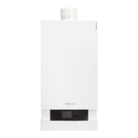
Fig. 15
■
If the device is not integrated into a CAN bus sys-
tem:
Switch
A
must not be set to "ON".
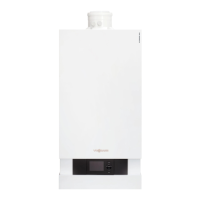
■
If the device is integrated into a CAN bus system and
is located at the beginning or end of this system (not
in the middle) of the CAN bus system (connected to
only one plug
lA
): Set switch
A
to "ON".
Fig. 16
A Heat generator / HMU heat management unit
B CAN bus cable
C CAN bus other subscribers
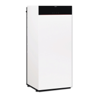
■
If the device is integrated into a CAN bus system and
is not located at the beginning or end of the CAN
bus system (both plugs
lA
connected): Do not set
switch
A
to "ON".
Fig. 17
Power supply for accessories at plug lH/aBH (230 V ~)
When positioned in wet rooms, accessories outside
the wet area must not be connected to the power sup-
ply at the HMU heat management unit. If the boiler is
not sited in a wet room, the power supply for accesso-
ries can be connected directly to the HMU heat man-
agement unit. This connection is switched directly with
the ON/OFF switch of the appliance.
If the total system current exceeds 6 A, connect one or
more extensions directly to the mains supply via an
ON/OFF switch (see next chapter).
Installation sequence
Electrical connections (cont.)
6151778
Installation