6
1. Information Disposal of packaging ............................................................................ 8
Symbols ................................................................................................. 8
Intended use .......................................................................................... 8
Product information ................................................................................ 9
■
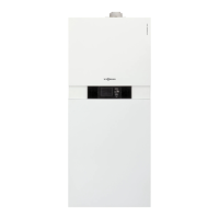
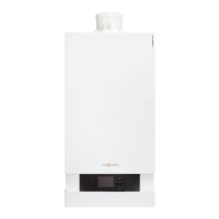
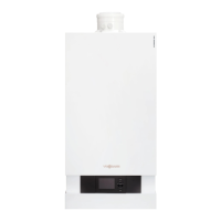
Vitodens 222-F, type B2TF ................................................................. 9
System examples .................................................................................. 9
Spare parts lists ..................................................................................... 9
2. Preparing for installation Handling ................................................................................................. 10
Siting in recesses ................................................................................... 10
Relocating the ON/OFF switch and electrical connections (if neces-
sary) ....................................................................................................... 10
Preparing for boiler installation .............................................................. 11
■
Safety assembly to DIN 1988 and EN 806 ......................................... 14
3. Installation sequence Siting the boiler ...................................................................................... 15
■
Type plate ........................................................................................... 15
Removing the front panel ....................................................................... 16
Connections on the heating water and DHW sides ............................... 17
■
DHW circulation connection (potable water) ...................................... 17
Filling the trap with water ....................................................................... 17
Flue gas connection ............................................................................... 18
Gas connection ...................................................................................... 19
Electrical connections ............................................................................ 20
■
Opening the HMU wiring chamber ..................................................... 20
■
On-site connections to the HMU heat management unit .................... 21
■
Outside temperature sensor
!
.......................................................... 21
■
Connecting the low loss header sensor
)
........................................ 21
■
Connecting the circulation pump to P2 ............................................... 22
■
Floating switching contact connection ................................................ 22
■
Checking the CAN bus terminator switch setting ............................... 22
■
Power supply for accessories at plug
lH
/
aBH
(230 V ~) ..................... 23
■
Power supply
fÖ
................................................................................. 25
■
WiFi operational reliability and system requirements ......................... 25
■
Routing connecting cables/leads ........................................................ 26
Closing the wiring chamber ................................................................... 26
Fitting the front panel and programming unit ......................................... 27
4. Commissioning, inspec-
tion, maintenance
Steps - commissioning, inspection and maintenance ............................ 28
5. System configuration
(parameters)
Calling up parameters ............................................................................ 59
General .................................................................................................. 59
Boiler ...................................................................................................... 61
DHW ...................................................................................................... 64
Heating circuit 1, Heating circuit 2, Heating circuit 3, Heating circuit 4 .. 65
Subscriber numbers of connected extensions ....................................... 70
6. Diagnosis and service
checks
Service menu ......................................................................................... 72
■
Service menu ...................................................................................... 72
Changing the service password ............................................................. 72
Resetting all passwords to delivered condition ...................................... 73
Diagnosis ............................................................................................... 73
■
Checking operating data ..................................................................... 73
Calling up messages (message history) ................................................ 73
Checking outputs (actuator test) ............................................................ 74
7. Troubleshooting Fault display on the programming unit ................................................... 77
Overview of electronics modules ........................................................... 78
Fault messages ..................................................................................... 79
Index
Index
6151778