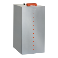
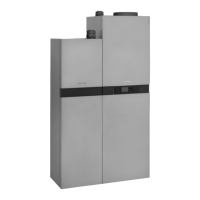
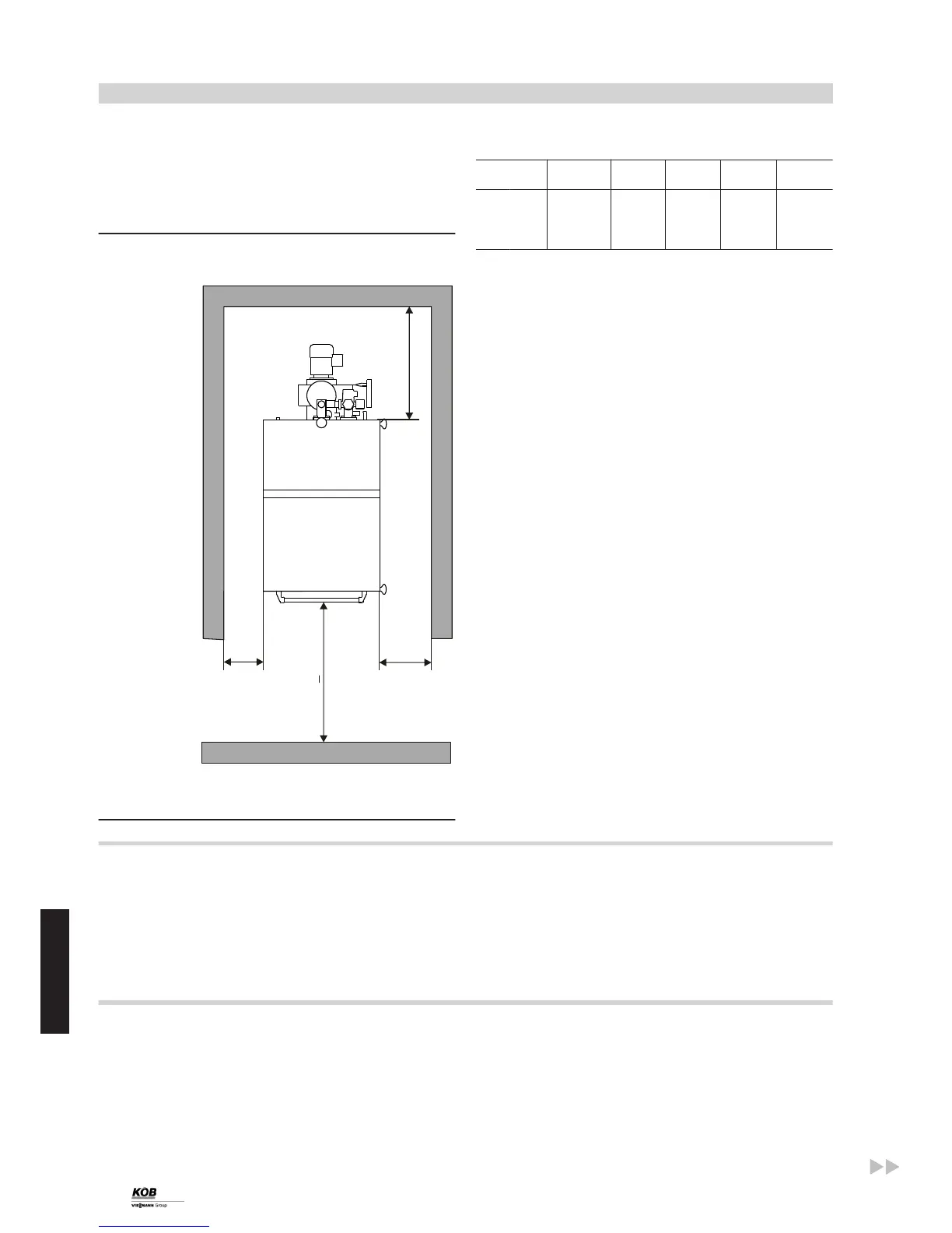
Wall clearances
Pyromat
ECO...
35 – 65 61 81 101 151
a mm ≥ 200 ≥ 400 ≥ 400 ≥ 400 ≥ 400
b mm 600 730 730 730 730
c mm 600 800 800 800 800
d mm 800 800 800 800 800
Note
If an oil burner is used on the boiler, dimension a is increased if the
burner is fitted on the left, or dimension c if the burner is fitted on the
right.
Siting
The following points must be observed for siting:
■ Avoid air contamination by halogenated hydrocarbons (e.g. as con-
tained in sprays, paints, solvents and cleaning agents)
■ Avoid very dusty conditions
■ Avoid high levels of humidity
■ Prevent frost and ensure good ventilation
7.2 Connection on the flue gas side
The boiler is equipped with a flue gas fan, therefore the combustion
equipment does not require a draught.
The chimney must be designed in the same way as for combustion
equipment with a pressure-jet oil or gas burner without draught require-
ment (flue gas temperature at rated load 160 - 200 °C).
To prevent the risk of soot contamination, provision must be made for
an insulated chimney.
The route from the flue gas fan to the chimney should be as short as
possible. 90° bends should be avoided wherever possible.
Flue pipes more than 1 m long should be insulated.
The chimney should be connected rising at an angle of 30 - 45°. The
flue pipe, including inlet to the chimney, must be gas-tight.
7.3 Water connection
Sizing of the heating water buffer cylinder to EN 303-5
Minimal cylinder volume for a typical Q
H
with T
B
× Q
N
for dry beech
wood.
V
cyl.
Buffer cylinder capacity in litres
Q
N
Rated heating output in kW
Design information
44
PYROMAT ECO
7
5822 546 GB