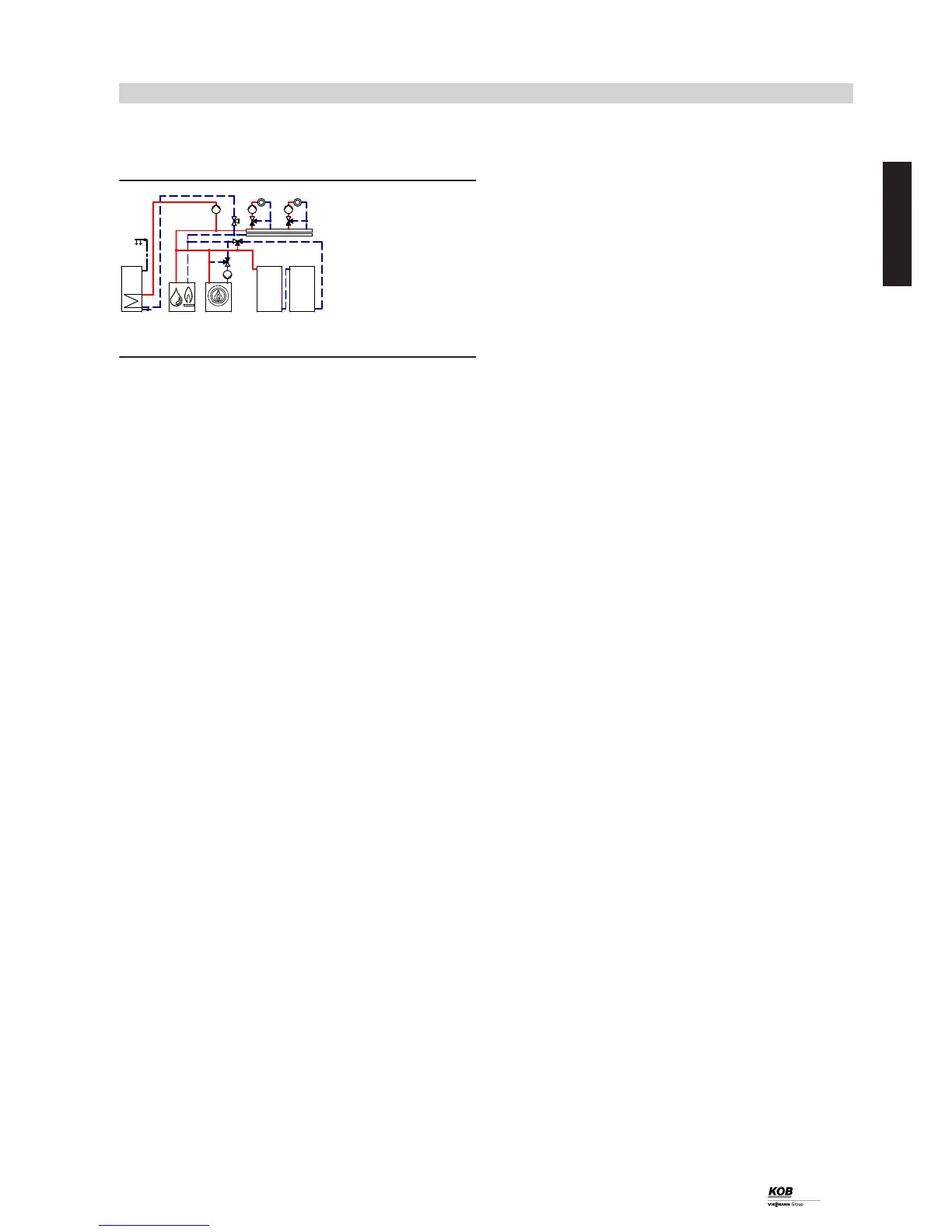
8.2 Pyromat Eco with oil/gas boiler, two heating circuits with mixer, heating water buffer
cylinder and DHW heating with DHW cylinder
ID: 4605385_1304_04
Applications
Heating system with log boiler, oil/gas boiler, with one or several heat-
ing circuits with 3-way mixer, heating water buffer cylinder plus DHW
heating.
Main components
■ Pyromat Eco
■ Ecotronic boiler control unit
■ Oil/gas boiler
■ Vitotronic 200, type KO1B, KO2B or KW6B
■ Return temperature raising facility
■ Heating water buffer cylinder
■ DHW cylinder
■ Buffer cylinder control valve
Function description
In order to achieve the required set temperatures in heating circuits
tP
/
zP
or for DHW heating
uP
, the Pyromat Eco
1
runs through the
following operating phases:
■ Heat up
■ Load operation
■ Residual heat utilisation
■ Drawing [heat] from the buffer cylinder
These are shown on the control unit display.
Heat up
Boiler
1
starts after charging and lighting the fuel. Initially, the air
dampers are zeroed.
Load operation
If the flue gas temperature exceeds 120 °C or the residual oxygen
content is less than 15 % (for 2 minutes), the air dampers enter their
controlled mode. For this, the air dampers are constantly regulated to
the respective set value via the value of the actual residual oxygen
content.
The actual flue gas temperature will be prevented from exceeding its
max. value by the flue gas fan and the adjustment of the primary air
dampers.
Residual heat utilisation
The residual heat utilisation phase begins if the flue gas temperature
falls below 100 °C. Buffer cylinder control valve
rT
remains closed and
boiler control valve
4
remains fully open for as long as the boiler flow
temperature is higher than the set system temperature.
Drawing [heat] from the buffer cylinder
If the boiler flow temperature falls below the set system temperature,
the heat for heating circuits
tP
/
zP
or for DHW heating
uP
is drawn
from heating water buffer cylinders
rP
/
rQ
. For this purpose, boiler
control valve
4
is completely closed and buffer cylinder control valve
rT
fully opened.
Return temperature raising facility
The Pyromat Eco
1
requires a minimum return temperature. When
boiler circuit pump
3
starts, boiler control valve
4
opens the path
from the central heating return to the Pyromat Eco
1
in line with the
increasing return temperature and closes the path from the boiler flow
to the boiler return (bypass).
As soon as boiler control valve
4
is fully open, buffer cylinder control
valve
rT
takes over return temperature raising.
Charging the heating water buffer cylinder
During the combustion phase, heating circuits
tP
/
zP
/
uP
are supplied
with heat first of all by boiler circuit pump
3
. As soon as the consum-
ers enter controlled mode, the heat not required for heating purposes
is routed via buffer cylinder control valve
rT
into the heating water
buffer cylinder, maintaining a precise temperature stratification. Fol-
lowing burnout, the residual boiler heat is utilised by the buffer charging
management, before the consumers are supplied by heating water
buffer cylinders
rP
/
rQ
.
Heating by the Pyromat Eco
The heat is routed to the heating distributor by boiler circuit pump
3
if the boiler water temperature of the Pyromat Eco
1
exceeds 65 ºC.
At this point, 3-way mixers
tR
/
zR
regulate the flow temperature in
accordance with the specified heating curve in weather-compensated
mode.
Heating by the heating water buffer cylinder (heat drawn from the
buffer)
If the boiler flow temperature falls below the set system temperature,
the heat for heating circuits
tP
/
zP
or for DHW heating
uP
is drawn
from heating water buffer cylinders
rP
/
rQ
. For this purpose, boiler
control valve
4
is completely closed and buffer cylinder control valve
rT
fully opened. The heat required to supply the heating circuits is
drawn from the heating water buffer cylinders using heating circuit
pumps
tE
/
zE
. The flow temperatures are also regulated in weather-
compensated mode via 3-way mixers
tR
/
zR
.
Heating by the oil/gas boiler
Boiler control unit
2
of Pyromat Eco
1
enables oil/gas boiler
eP
via
contactor relay
eI
if the actual boiler water and heating water buffer
cylinder temperatures are below the set system temperature. At the
same time, buffer cylinder control valve
rT
closes and the two-way
valve in the boiler return of oil/gas boiler
eP
opens. Oil/gas boiler
eP
now takes over heat supply for the heating distributor in weather-com-
pensated mode. The flow temperatures are also regulated in weather-
compensated mode via 3-way mixers
tR
/
zR
by boiler control unit
2
of Pyromat
1
.
DHW heating
When the temperature at DHW cylinder sensor
uW
falls below the
value selected, circulation pump for cylinder heating
uE
starts and
DHW cylinder
qP
is heated. Circulation pump for cylinder heating
uE
continues running until the DHW temperature at cylinder temperature
sensor
uW
has reached its set value. To optimise cylinder heating,
regulating valve
uR
takes the flow rate higher or lower, depending on
the temperature spread between cylinder temperature sensor
uW
and
return temperature sensor
uT
.
With DHW heating by oil/gas boiler
eP
, the boiler water temperature
of oil/gas boiler
eP
is raised for DHW heating through a demand from
extension kit
uQ
via external EA1 extension
eW
and contactor relay
uZ
.
Application examples
(cont.)
PYROMAT ECO
53
5822 546 GB
8