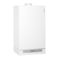
Control Connections
145144
EXTERNAL
DEMAND
31 2
145
31 2
144
31 2
143
1
2 3
1
2
3
1
2
3
143
Power/Pump module
Fig. 44
49
Electrical Connections (continued)
External switching of heating program/External heat demand / External blocking
aVD - External blocking terminals 2-3
External demand terminals 1-2
External heating program
changeover terminals 1-2
The allocation of the function
“external heating program
changeover” is set via coding
address ‘91’
See Start-up/Service
Instructions with regard to
changing the coding addresses.
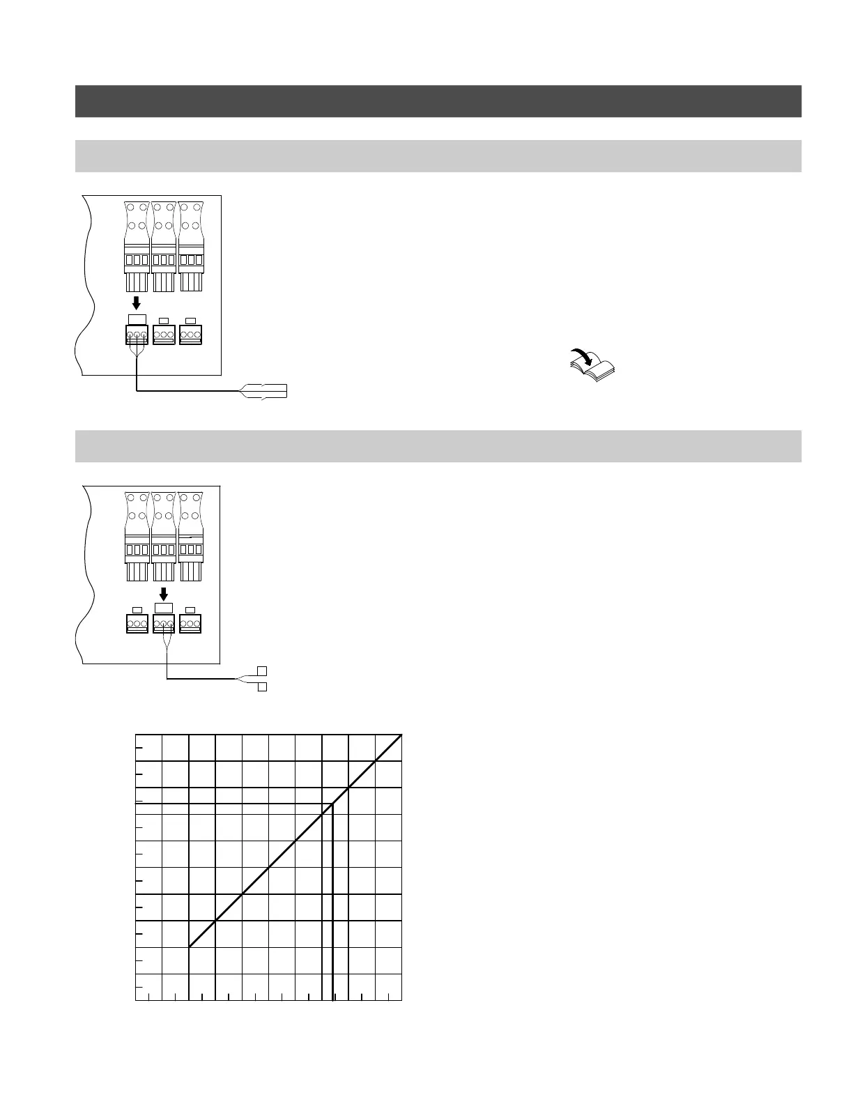
External 0-10 volt signal connection
1. Connect the external 0-10 V signal to
plug aVF located in the Power/Pump
module (shown in Fig. 45).
2. Ensure correct polarity.
3. See Fig. 46 for maximum possible
boiler water temperature and
required signal.
* 7.4 VDC at 165ºF / 74ºC for
boiler models WB2B 45, 60
5418 909 v1.6
145
144
143
EXTERNAL
SIGNAL
0-10 V
31 2
145
31 2
144
31 2
143
1
2
3
1
23
1
2 3
+
--
+
--
Power/Pump module
Fig. 45
0V
1V
2V
3V
4V
5V
6V 7V
8V
9V
10V
*
7.4V
212ºF/100ºC
203ºF/95ºC
194ºF/90ºC
185ºF/85ºC
176ºF/80ºC
158ºF/70ºC
167ºF/75ºC
149ºF/65ºC
122ºF/50ºC
131ºF/55ºC
144ºF/60ºC
104ºF/40ºC
113ºF/45ºC
59ºF/15ºC
77ºF/25ºC
95ºF/35ºC
50ºF/10ºC
68ºF/20ºC
86ºF/30ºC
41ºF/5ºC
Fig. 46
 Loading...