5
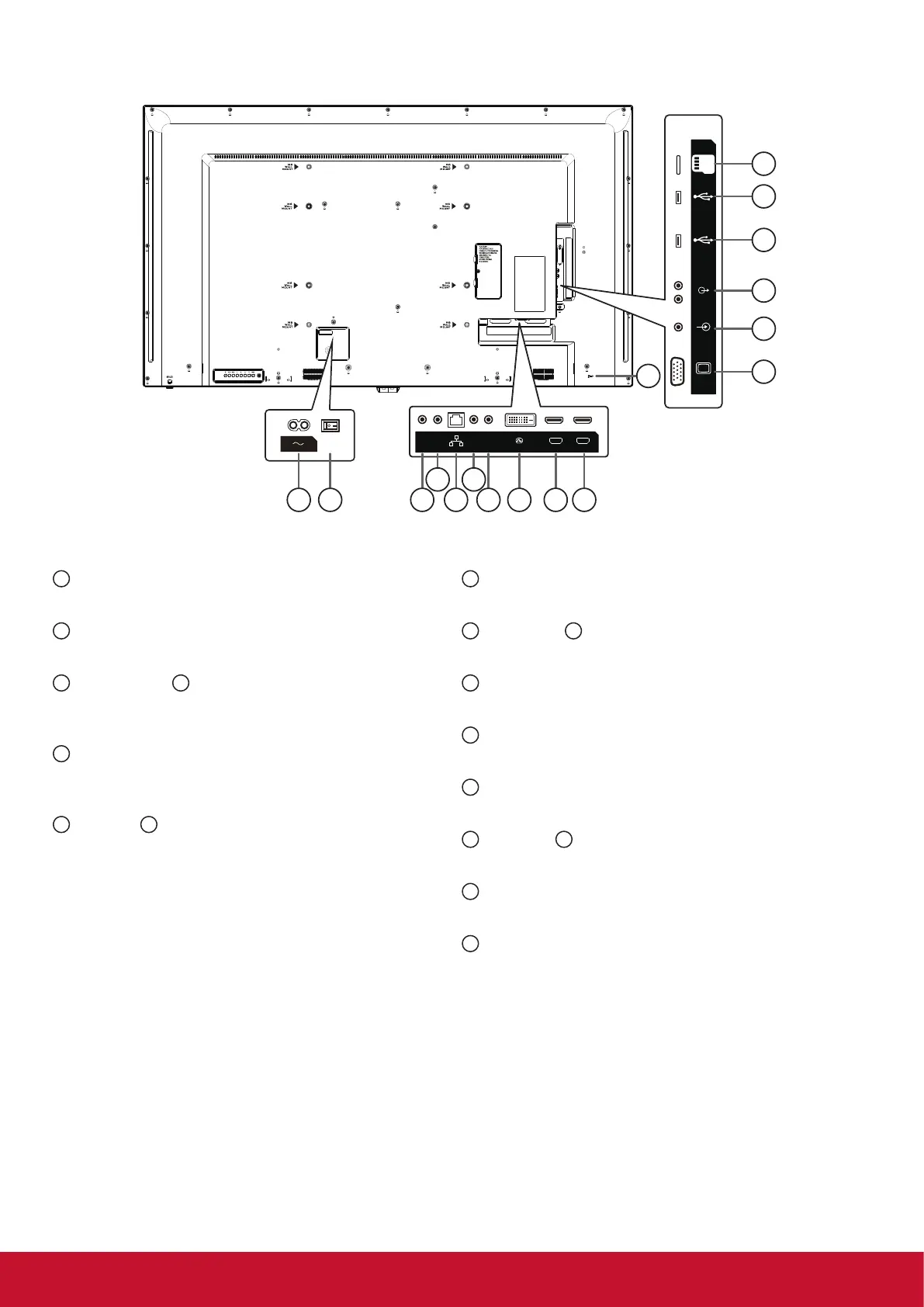
2.2. Input/Output Terminals
PC LINE IN
VGA IN
USB 3.0
USB 2.0
AUDIO OUT
MICRO SD
11
17
12
13
15
14
16
1 32 5
4 6
7 98 10
HDMI 1 IN HDMI 2 IN
IR-IN IR-OUT
RJ45
RS232
OUT
RS232
IN
DVI IN
1
AC IN
AC power input from the wall outlet.
2
MAIN POWER SWITCH
Switch the main power on/off.
3
RS232 OUT /
4
RS232 IN
RS232C network output / input for the loop-through
function.
5
RJ-45
LAN control function for the use of remote control
signal from control center.
6
IR OUT /
7
IR IN
IR signal output /input for the loop-through function.
NOTES:
• This display’s remote control sensor will stop
working if the jack [IR IN] is connected.
• To remotely control your A/V device via this
display, refer to page 14 for or IR Pass Through
connection.
8
DVI-D IN
DVI-D video input.
9
HDMI1 IN /
10
HDMI2 IN
HDMI video/audio input.
11
VGA IN (D-Sub)
VGA video input.
12
PC LINE IN
Audio input from VGA source (3.5mm stereo phone).
13
AUDIO OUT
Audio output to external AV device.
14
USB 2.0 /
15
USB 3.0 PORT
Connect your USB storage device
16
MICRO SD CARD
Connect your MICRO SD CARD
17
Security LOCK
Used for security and theft prevention.