15
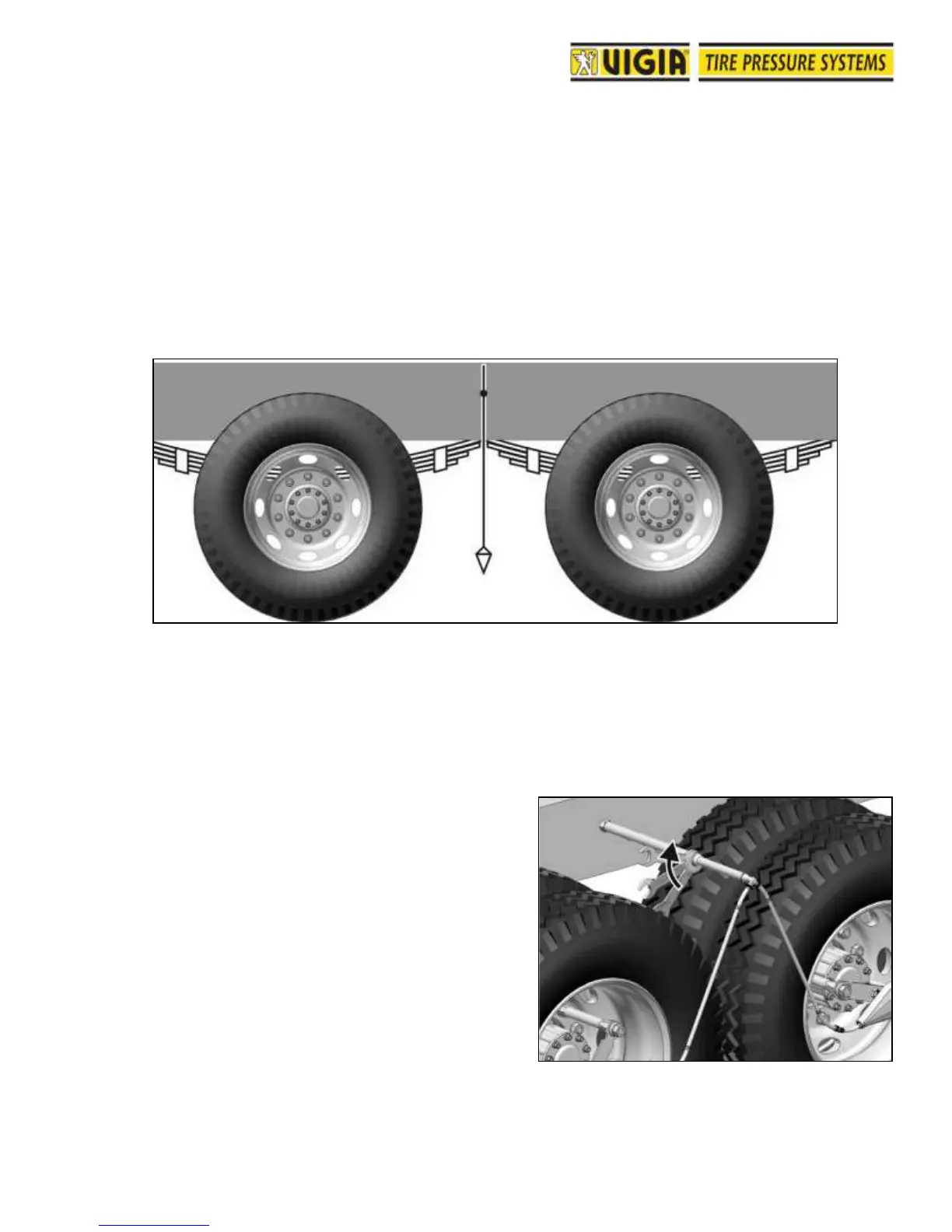
C2. Double Axles (Fig. 49)
Note: This procedure is applied only if the air pressure
in the tires in both axles is the same. If that is not the
case, refer to the procedure for single axles.
1- Find a bolt or hole approximately midway between both axles, and at a height that will avoid
any rubbing to the mounting pipe, even with the suspension working at load limit.
2- Take the selected bolt out.
3- Secure the body coupling mounting pipe with the
bolt provided. Tighten with a torque of
approximately 115 lbs/sqft.
The body coupling mounting pipe must remain
with the VIGIA hose's outlet hole facing down.
4- Install body coupling to the adjustable mounting
pipe as indicated in Figure 48 above. Note that
body coupling’s spacer is removed.
5- Pass the required hose length through the hole
and connect the body coupling.
6- Screw the mounting pipe end with 15 lbs/sqft.
torque turning the hose at the same time to
avoid strangling.
7- Adjust the length of the adjustable mounting
pipe making sure that body coupling end is not
exposed. Fix position with corresponding conic
nut.