Page 10 ACM Telephone System – AMC-M-A A100K 10430 v.1.0
3.4 Power Supply
The ACM-M-A-V2 is powered from 230 VAC mains with automatic
switchover to 230 VAC UPS or 24 VDC emergency power.
All internal power cabling is ready made from the factory and routed in
cable conducts.
z Connect 230 VAC mains to L and N terminals on the X1 circuit breaker
z Connect mains earth to the ground bar
z Connect 230 VAC UPS power to L and N terminals on the X2 circuit
breaker if this backup power is used
z Connect 24 VDC emergency power to the + and - terminals on the
X3 circuit breaker if this backup power is used
The ACM-M-A-V2 rack will consume max. 150 Watts. The 230 V power
cable must have a minimum dimension of 1.5 mm
2,
and the 24 V cable
should be 2.5 mm
2
.
The 230 VAC mains outlet X7 is used for service purposes.
See section 9 for schematic on internal wiring.
3.4.1 Power failure
Three power fail relays are included to indicate type of failure. Each
relay has a NO/NC switch-over contact to indicate Power good/fail. Note
that the relays are activated when the actual power is OK, which means
that the NO contact is closed and NC is open in normal condition.
- X4 is released if the 230 VAC power disappear (mains and UPS)
- X5 is released if the 24 VDC emergency power disappear
- X6 is released if the 24 VDC output power from AMC-E7 disappear
3.5 Line Connection Module (LCM)
All line connections are made to the Line Connection Module board.
This board substitutes the former 6 x Line Termination boards.
This module also substitute the Power Distribution board, VA-502 Relay
Unit board with 6 RCO relays and VA-503 Filter and Speech Adapter
board with 2 audio outputs, 1 audio input and PTT relay if these
functions are used.
The module has connectors for:
z 24 VDC Power
- Input
- Output (not used)
- 3 x 1 A fused output (not used)
- 6 x relay controlled RCO outputs, 1 A common fuse
z Linepoints
- Max. 60 analogue telephone lines with 5 x ATLB12 boards
- Max. 5 4-wire intercom stations
z RCO
- 1 x relay contact for PA control
- 5 x relay contacts, potential free or +24 V (switch selection)
z RCI (Needs APC board, not used in ACM-M-A-V2)
- 6 x inputs
z PA/GA or radio input (Needs APC board, not used in ACM-M-A-V2)
- 6 x potential free 600 ohm, 0 dB lines
z Radio/Walkie-Talkie interface (Needs APC board, not used in ACM-
M-A-V2)
- Potential free adjustable audio in and out
- RCO relay can be used for PTT control
z PA audio output
- Audio output for PA with possibility for monitor intercom station in
parallel
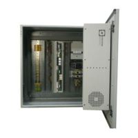
Figure 6 Power connection
Figure 7 Line Control Module
X3
X2
X1
X4
X5
X6
X7
230 VAC
UPS
230 VAC
mains
24 VDC
+
L
L
N
N
AC fail
DC fail
SYSTEM fail
SERVICE
OUTLET
230 VAC
NO
NO
NO
NC
NC
NC
 Loading...