A100K 10430 v.1.0 ACM Telephone System – AMC-M-A Page 9
3 HW INSTALLATION GUIDE
3.1 System Rack Mounting
The ACM-M-A-V2 system rack is made for wall mounting. Mount the
cabinet at a convenient height, bottom about 1.2 m above the floor.
Make sure there is enough space around the rack for connection and
servicing.
z Rack Temperature: Recommended: +18
o
C to +25
o
C
Extreme: 0°C to +55°C
z Max. humidity: >95% RH @ 25°C / 93% RH @ 55°C
z Compass safety: Distance to ACM-rack: 325 cm
Distance to telephones: 95 cm
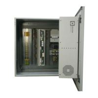
3.2 Insert Feature Boards
Open the front cover of the AlphaCom E7 exchange using a Philips
screwdriver.
The AMC-IP board is inserted in slot position 7. This is the rightmost slot
position.
The ASLT intercom/PA audio board is inserted in slot pos 2.
The ATLB12 subscriber line boards are inserted in slot positions 1 and 3
for the smallest exchange. Slot pos. 4-6 are used for additional lines.
A fully equipped exchange can support up to 60 analogue telephones
and 6 VMP intercom stations.
The exchange is ready equipped according to customer’s order:
ACM-M-A24 2 x ATLB12 max 24 telephones pos 1+3
ACM-M-A36 3 x ATLB12 max 36 telephones pos 1+3-4
ACM-M-A48 4 x ATLB12 max 48 telephones pos 1+3-5
ACM-M-A60 5 x ATLB12 max 60 telephones pos 1+3-6
3.3 Connection terminals
Connectors and terminals for power and external
equipment are accessible in the rear of the ACM-
M-A-V2 cabinet. To access the connectors, open
the cabinet door and swing out the AlphaCom E7
exchange.
Cable inlets are in the bottom of the cabinet and
there is a cable fastening bar in the lower part. All
internal cabling is ready made from the factory and
routed in cable conducts.
The ACM-M-A-V2 system is shipped with an ACM
Programming and Cable Reference list. This list
shows how the external wiring shall be connected
to the different terminal blocks. See section 4 for
example.
min.
200 mm
min.
200 mm
600 mm
1000 mm
350 mm
Figure 4 Card positions in the
AlphaCom E7 exchange
Figure 3 Mounting rack
Figure 5 External connectors and terminals
ASLT
ATLB12
ATLB12
ATLB12
ATLB12
POWER
ATLB12
AMC-IP
1 2 3 4 5 6 7
230 VAC UPS
230 VAC mains
Relay, mains/UPS
24 VDC input
AC fail relay
24 VDC in/out
DC fail relay
Ground bar
FXO terminals
for MP114
X3
X2
X1
X4
X5
X6
X7
Intercom
lines / PA
 Loading...