A100K 10430 v.1.0 ACM Telephone System – AMC-M-A Page 13
z Set switch S9 to ON to simulate audio-out load when monitor station
is missing
z Set switch S10 to ON to simulate audio-in load when monitor station
is missing
z Leave switches S7, S8 and S17 OFF.
z Set volume control RP3, OUT2, to mid pos. This must be
readjusted to 1±0.5 Vrms during live test
z Set switch S1 in Potent. Free position for chime activation.
3.7.2 Intercom station as PA monitor
z Connect the PA amplifier and chime relay as described above.
z Connect an intercom station to line point 8A/B/C/D
z Set switch S18 to ON to activate the audio filter
z Leave all other switches OFF
PA on OUT2
Audio
STATION CONNECT TO S9 S10 S18
NO Normal 8A/B/C/D NA OFF OFF
YES NO - ON ON ON
YES PA Monitor 8A/B/C/D OFF OFF ON
See section 6.6 for PA programming.
3.8 External Communication
An optional Analogue Telephone Gateway MP-114
provides external communication towards the
satellite communication system using 2 or 4
analogue trunks. Optionally, MP-118 provides up
to 8 trunks.
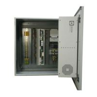
The gateway and screw terminal block are
mounted on the left side wall inside the cabinet.
The Ethernet 1 output on the exchange backplane
is connected to the Ethernet input on the gateway.
A and B wires on pin 3 and 4 in the RJ11 FXO
outputs are connected to the FXO screw terminal
block.
The Gateway and LAN interface are ready
mounted and wired from the factory if included in
the customer’s order.
Connect the analogue trunks to terminals FXO 1-8
See the SIP Gateway Configuration Manual A100K
10333 for further description of AudioCodes
MP114/118.
Figure 12 Wiring of Analogue
Telephone Gateway
FXO
RS-232
Ethernet
MP-114
1
2
34
36
31
1
P5
P6
N1
N5
N4
N2
N3
24V DC
Out
24V AC In
+
24V DC
In
+
_
_
Program level
RCO 1 - 6
1
RCO 7 - 12
P6
P5
RCI 2
RCI 1
Eth 0
Eth 1
Serial Port 0
Serial Port 1
USB
485 422
1
12
6
18
24
30
7
13
19
25
1
2
3
AC-
GND
DC-
GND
A
A
A
A
 Loading...