CAUTION!
Please consider that when replacing an already coded
electronic module, this is always be replaced by an elec-
tronic module with the same coding.
Even with an existing coding on the terminal module, you
can plug an electronic module without coding. The user is
responsible for the correct usage of the coding pins. VIPA
assumes no liability for incorrectly attached electronic
modules or for damages which arise due to incorrect
coding!
The modules were directly be mounted to the mounting rail and so
connected to the backplane bus and the power supply for the elec-
tronic and power section. Up to 64 modules may be mounted. Please
consider here that the sum current of the electronic power supply
does not exceed the maximum value of 3A. By means of the power
module 007-1AB10 the current of the electronic power supply may be
expanded with 2A.
Ä
Chapter 2.6 ‘Wiring’ on page 22
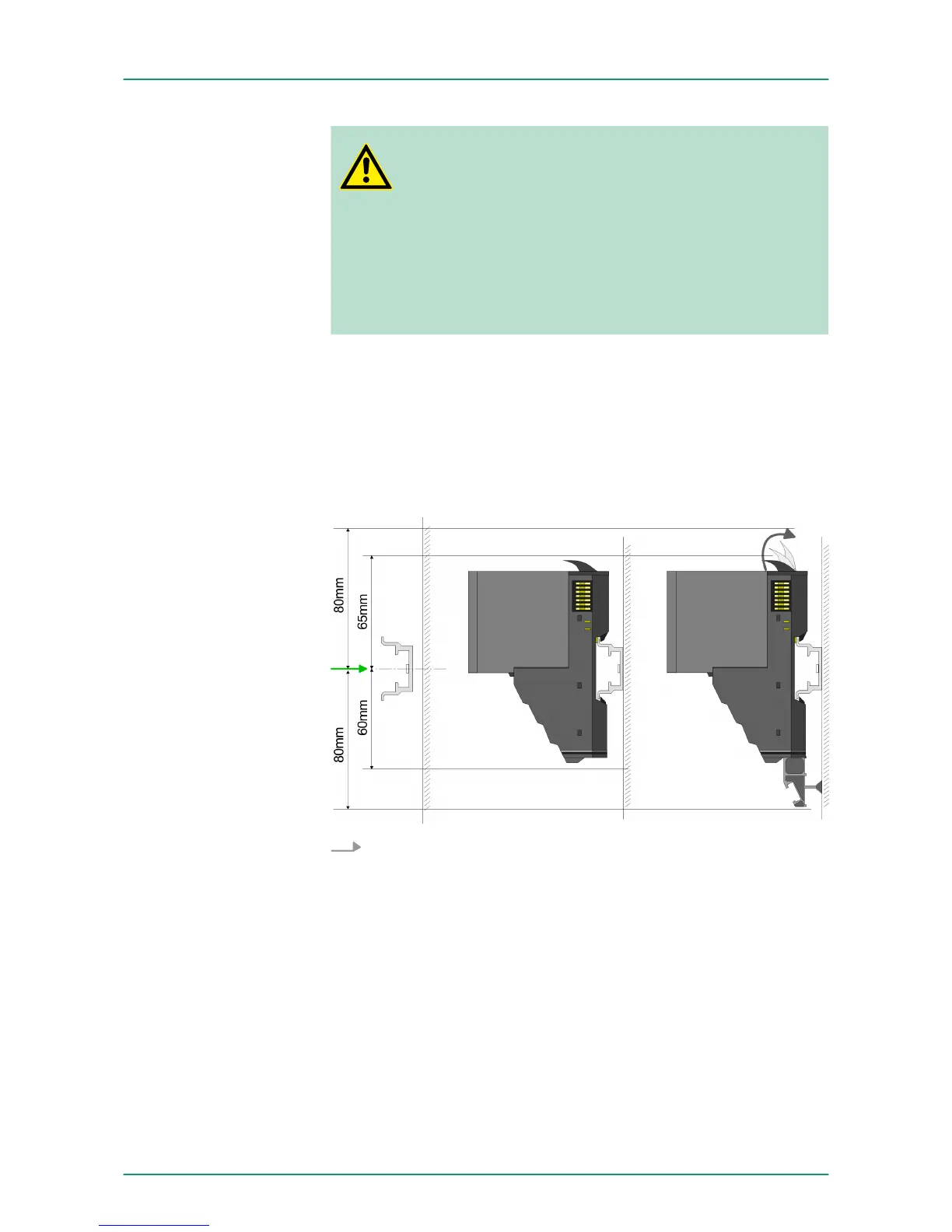
Mounting rail
Mount the mounting rail! Please consider that a clearance from
the middle of the mounting rail of at least 80mm above and
60mm below, respectively 80mm by deployment of shield bus
carriers, exist.
Mounting Proceeding
VIPA System SLIO Basics and Assembly
Installation
HB300 | FM | 050-1BA00 | GB | 14-36 15